SLAU292G November 2009 – July 2015
- Read This First
- 1eZ430-Chronos™ Overview
- 2Getting Started
-
3eZ430-Chronos Software
- 3.1 Overview
- 3.2
eZ430-Chronos Demo Software
- 3.2.1
Detailed Feature Overview - Modes Using the Top LCD Line
- 3.2.1.1 Time Mode
- 3.2.1.2 Alarm Mode
- 3.2.1.3 Temperature Mode
- 3.2.1.4 Altimeter Mode
- 3.2.1.5 Heart Rate Mode - RF Additional accessory or eZ430-Chronos Control Center heart rate simulation required.
- 3.2.1.6 Speed Mode - RF Additional accessory or eZ430-Chronos Control Center heart rate simulation required.
- 3.2.1.7 Tilt Mode
- 3.2.2
Detailed Feature Overview - Modes Using the Bottom LCD Line
- 3.2.2.1 Date Mode
- 3.2.2.2 Stopwatch Mode
- 3.2.2.3 Battery Voltage Mode
- 3.2.2.4 Acceleration Mode - RF
- 3.2.2.5 PowerPoint Mode - RF
- 3.2.2.6 Sync Mode - RF
- 3.2.2.7 Calorie/Distance Mode - RF Additional accessory or eZ430-Chronos Control Center heart rate simulation required.
- 3.2.2.8 Wireless Update - RF
- 3.2.1
Detailed Feature Overview - Modes Using the Top LCD Line
- 3.3 eZ430-Chronos Control Center PC Software
- 3.4 eZ430-Chronos Data Logger
- 3.5 Data Logger PC Software
- 3.6
eZ430-Chronos Software Projects
- 3.6.1 IDE Installation
- 3.6.2 eZ430-Chronos Software Flow
- 3.6.3 eZ430-Chronos Wireless Update Feature
- 3.6.4 eZ430-Chronos Firmware
- 3.6.5 eZ430-Chronos GUI Sources
-
4eZ430-Chronos Hardware
- 4.1 Programming the eZ430-Chronos Wrist Module: Disassembly and Assembly of the Housing
- 4.2 Functional Description of the eZ430-Chronos Wrist Module
- 4.3 Functional Description of the eZ430-Chronos RF Access Point
- 4.4 Functional Description of the eZ430-Chronos Debug Interface
- 4.5 Schematics, Layout, BOM, and LCD
- 4.6 Access Point Schematics, Layout, and BOM
- AFrequently Asked Questions
- BDetailed Hardware Driver Installation Guide
- Revision History
4.1.1 Disassembly of eZ430-Chronos Wrist Module
- Open screws on back of the wrist module. Use the included Phillips screwdriver.
- Remove the metal back of the wrist housing. Be careful not to damage the gasket between the wrist module and the metal back.
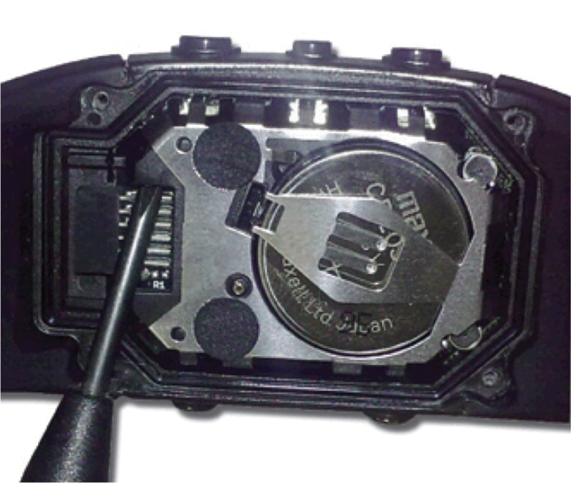
- Lift out the Chronos module. Use the screwdriver as shown in Figure 4-1.
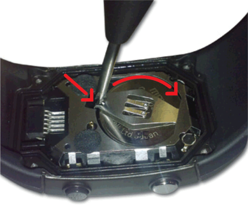
- Remove the battery before connecting the module to the emulator. Place the screwdriver tip between the battery and the battery holder (small metal tab) and push the tab away from battery (see Figure 4-2). Detailed instructions are shown in the eZ430-Chronos Disassembly and Assembly video on www.ti.com/chronoswiki.
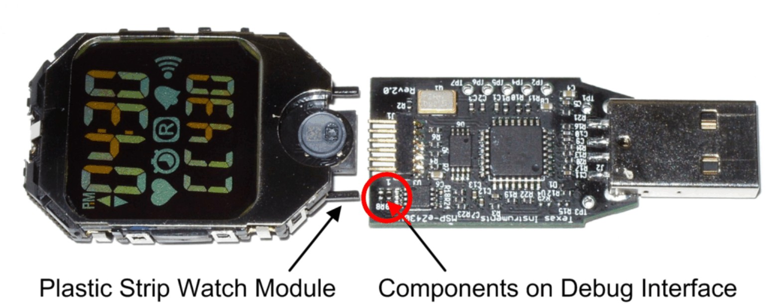
- Connect the Chronos module to the emulator. The Chronos module and the USB connector must be on the same side of the PCB as shown in Figure 4-3. Be careful when connecting the Chronos module, because its small plastic strips can get stuck at components on the emulator.
 Figure 4-1 Remove Chronos Module From Housing
  Figure 4-2 Remove Chronos Module Battery
 CAUTION
To prevent the battery from being charged, always remove the battery from the enclosure before connecting the Chronos module to an emulator.
WARNING
Properly dispose of the battery. Keep the battery out of the reach of children. If the battery is swallowed, contact a physician immediately.
 Figure 4-3 eZ430-Chronos Module Attached to eZ430-RF Debug Interface
 NOTE
- Never disassemble the Chronos module itself.
- Do not bend the metal strips that are used as contacts for the buttons.
- Be careful when connecting the Chronos module to the debug interface; its small plastic strips can get stuck at components on the emulator.