ZHCSHX7B November   2017  – May 2022 DLPC120-Q1

PRODUCTION DATA  

  1. 特性
  2. 应用
  3. 说明
  4. Revision History
  5. Pin Configuration and Functions
    1. 5.1 LED Driver Interface
    2. 5.2 DMD Temperature Interface
    3.     General Purpose I/O
    4. 5.3 Main Video and Data Control Interface
    5. 5.4 DMD Interface
    6. 5.5 Memory Interface
    7.     Board Level Test and Debug
    8.     Manufacturing Test Support
    9.     Test Point Interface
    10.     Power and Ground
  6. Specifications
    1. 6.1  Absolute Maximum Ratings
    2. 6.2  ESD Ratings
    3. 6.3  Recommended Operating Conditions
    4. 6.4  Thermal Information
    5. 6.5  Electrical Characteristics
    6. 6.6  Electrical Characteristics for I/O
    7. 6.7  Power Supply and Reset Timing Requirements
    8. 6.8  Reference Clock PLL Timing Requirements
    9. 6.9  Parallel Interface General Timing Requirements
    10. 6.10 Parallel Interface Frame Timing Requirements
    11. 6.11 Flash Memory Interface Timing Requirements
    12. 6.12 DMD Interface Timing Requirements
    13. 6.13 JTAG Interface Timing Requirements
    14. 6.14 I2C Interface Timing Requirements
  7. Parameter Measurement Information
    1. 7.1 Parallel Interface Input Source Timing
    2. 7.2 Design for Test Functions
  8. Detailed Description
    1. 8.1 Overview
    2. 8.2 Functional Block Diagram
    3. 8.3 Feature Description
      1. 8.3.1 Serial Flash Interface
      2. 8.3.2 Serial Flash Programming
      3. 8.3.3 DDR2 Memory Interface
      4. 8.3.4 JTAG and DMD Interface Test
      5. 8.3.5 Temperature Monitor Function
      6. 8.3.6 Host Command Interface
    4. 8.4 Device Functional Modes
      1. 8.4.1 External Video Mode
      2. 8.4.2 Splash Screen Mode
      3. 8.4.3 Test Pattern Mode
  9. Application and Implementation
    1. 9.1 Application Information
    2. 9.2 Typical Application
      1. 9.2.1 Design Requirements
  10. 10Power Supply Recommendations
    1. 10.1 Power Supply Filtering
  11. 11Layout
    1. 11.1 Layout Guidelines
      1. 11.1.1 PCB layout guidelines for internal ASIC PLL power
      2. 11.1.2 DLPC120-Q1 Reference Clock
        1. 11.1.2.1 Recommended Crystal Oscillator Configuration
      3. 11.1.3 General PCB Recommendations
      4. 11.1.4 PCB Routing Guidelines
      5. 11.1.5 Number of Layer Changes
      6. 11.1.6 Terminations
      7. 11.1.7 General Handling Guidelines for Unused CMOS-Type Pins
  12. 12Device and Documentation Support
    1. 12.1 第三方产品免责声明
    2. 12.2 Device Support
      1. 12.2.1 Device Nomenclature
        1. 12.2.1.1 Device Markings
    3. 12.3 Documentation Support
      1. 12.3.1 Related Documentation
    4. 12.4 接收文档更新通知
    5. 12.5 支持资源
    6. 12.6 Trademarks
    7. 12.7 Electrostatic Discharge Caution
    8. 12.8 术语表
  13. 13Mechanical, Packaging, and Orderable Information

封装选项

请参考 PDF 数据表获取器件具体的封装图。

机械数据 (封装 | 引脚)
  • ZXS|216
散热焊盘机械数据 (封装 | 引脚)
订购信息

说明

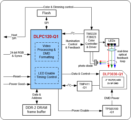
DLPC120-Q1 适用于汽车应用的 DMD 显示控制器是与三个数字微镜器件 (DMD) 之一(DLP3030-Q1、DLP3020-Q1 或 DLP3021-Q1)兼容的芯片组的一部分。DLPC120-Q1 的核心逻辑负责接受视频输入并对数据进行格式化以便在 DMD 上显示,同时还控制 RGB LED 来形成实时图像。DLPC120-Q1 还负责根据外部系统控制或 DMD 温度输入来控制 DMD 的上电和断电事件。通过与外部调光电路和微控制器结合,DLPC120-Q1 支持的宽调光范围 > 5000:1,适合于 HUD 应用。通常情况下,DLPC120-Q1 是主机处理器 I2C 接口的外围器件。

器件信息
器件型号(1)封装封装尺寸(标称值)
DLPC120-Q1NFBGA (216)17.00mm × 17.00mm
如需了解所有可用封装,请参阅数据表末尾的可订购产品附录。
GUID-29E69D96-2001-47D3-90C1-A901EB2CF095-low.gif典型系统图