ZHCUAD2C October 2016 – August 2021
4.1 Positive Supply and Test Points
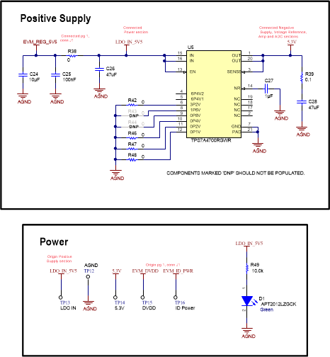
The analog supply of the ADC (AVDD = 5.3 V) is powered by the TPS7A4700RGWR (U5) low-dropout regulator (LDO). The input to this LDO is the regulated 5.5-V supply from the PHI. This LDO can be programed to different voltages by soldering or desoldering resistors R42 to R48.
A test point for each power supply is provided. Furthermore, a light-emitting diode (LED) is used to indicate when the 5.5-V supply from the PHI turns on. This power turns on shortly after the software is booted. The EVM is not powered until the software is started, so TI does not recommend connecting the external signal source until the EVM is powered. Figure 4-1 shows the positive supply and test points for the TPS7A4700RGWR.
 Figure 4-1 Positive Supply and Test
Points