TIDUE59A May 2018 – September 2020
- Description
- Resources
- Features
- Applications
- 1System Description
-
2System Overview
- 2.1 Block Diagram
- 2.2 Design Considerations
- 2.3 Highlighted Products
- 2.4 System Design Theory
- 3Hardware, Software, Testing Requirements, and Test Results
- 4Design Files
- 5Software Files
- 6Related Documentation
- 7Terminology
- 8About the Author
- 9Revision History
3.2.4 Test Results
The average current consumed by the CC3220, while the system was in the idle connected mode (connected to the AP and only receiving AP beacons or broadcast and multicast traffic) with an LSI of 400 milliseconds, was measured to be 377 µA on average, over multiple DTIM receptions. The power consumed while in the idle connected mode contributes the most to the overall average power consumption, because the system is expected to spend the majority of its active time in the idle connected state. Figure 3-15 shows a graph of the measured current.
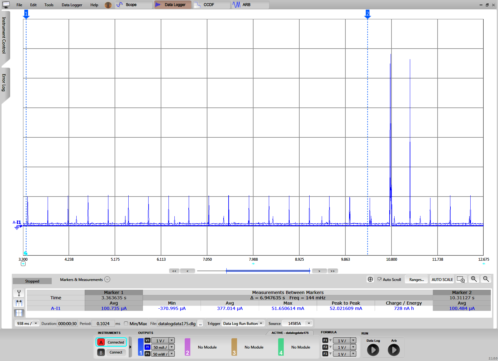 Figure 3-15 CC3220S Current Consumption Versus Time While in Idle Connected Mode With 400-ms LSI
When a message is sent to the TIDC-01005 from the cloud, the CC3220S receives an indication that the AP has buffered a packet for it through the DTIM. In response to the traffic indication, the CC3220S wakes up from low-power mode and polls the AP for the message. The impact on the system power consumption is different depending on which message is received. The first type of message considered is a lock or unlock command. When a lock or unlock command is received, the network processor wakes up, receives the message, and sends the command to the host MCU. The host MCU then parses the command and drives the motor in the appropriate direction for two seconds. The average current consumption of the CC3220S during a lock or unlock command was approximately 12.1 mA and Figure 3-16 shows the current consumption.
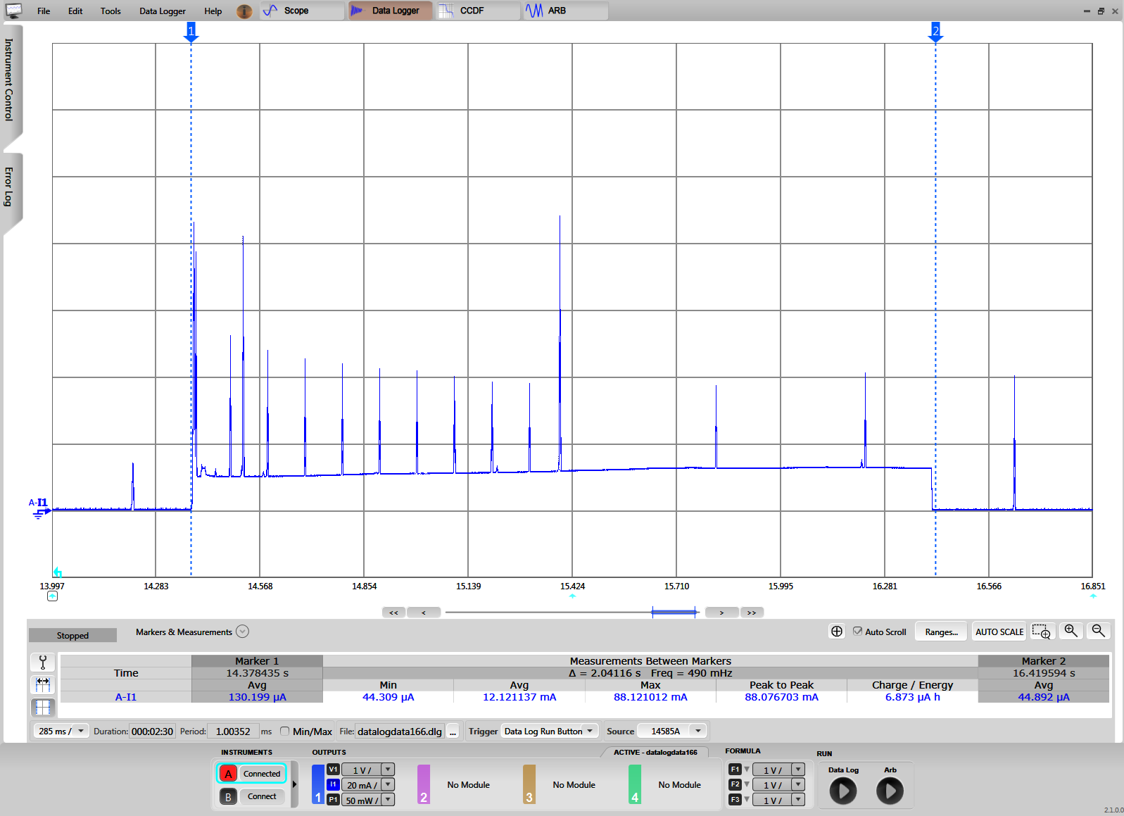 Figure 3-16 CC3220 Current Consumption During Lock and Unlock Cycle
In Figure 3-16, the first spike in current after the cursor represents when the network processor detects a message is ready for it and wakes up to poll the AP. After the message is received, the MCU is waken up by the network processor, and the message is sent to the MCU to be handled. The current consumption remains around the 11 to 12-mA level for the entire two seconds while the MCU is active and driving the motor. The smaller spikes in current that occur while the MCU is active and following the message reception represent AP beacon receptions. These beacon receptions occur because the CC3220S waits to resume LSI until a timeout occurs after a message reception. By not entering LSI immediately, the latency is reduced when multiple messages are sent to the system within a short interval without a large impact on power consumption.
The second type of message that can be received by the TIDC-01005 is a lock status request. When a lock status request is received, the network processor wakes up, receives the message, and sends the request to the host MCU. Then, the MCU parses the request and responds by sending a message indicating the lock state back to the cloud. The average current consumption of the CC3220S, in response to a lock status request, was found to be approximately 11.8 mA. Figure 3-17 shows a graph of the current consumption for the lock status case.
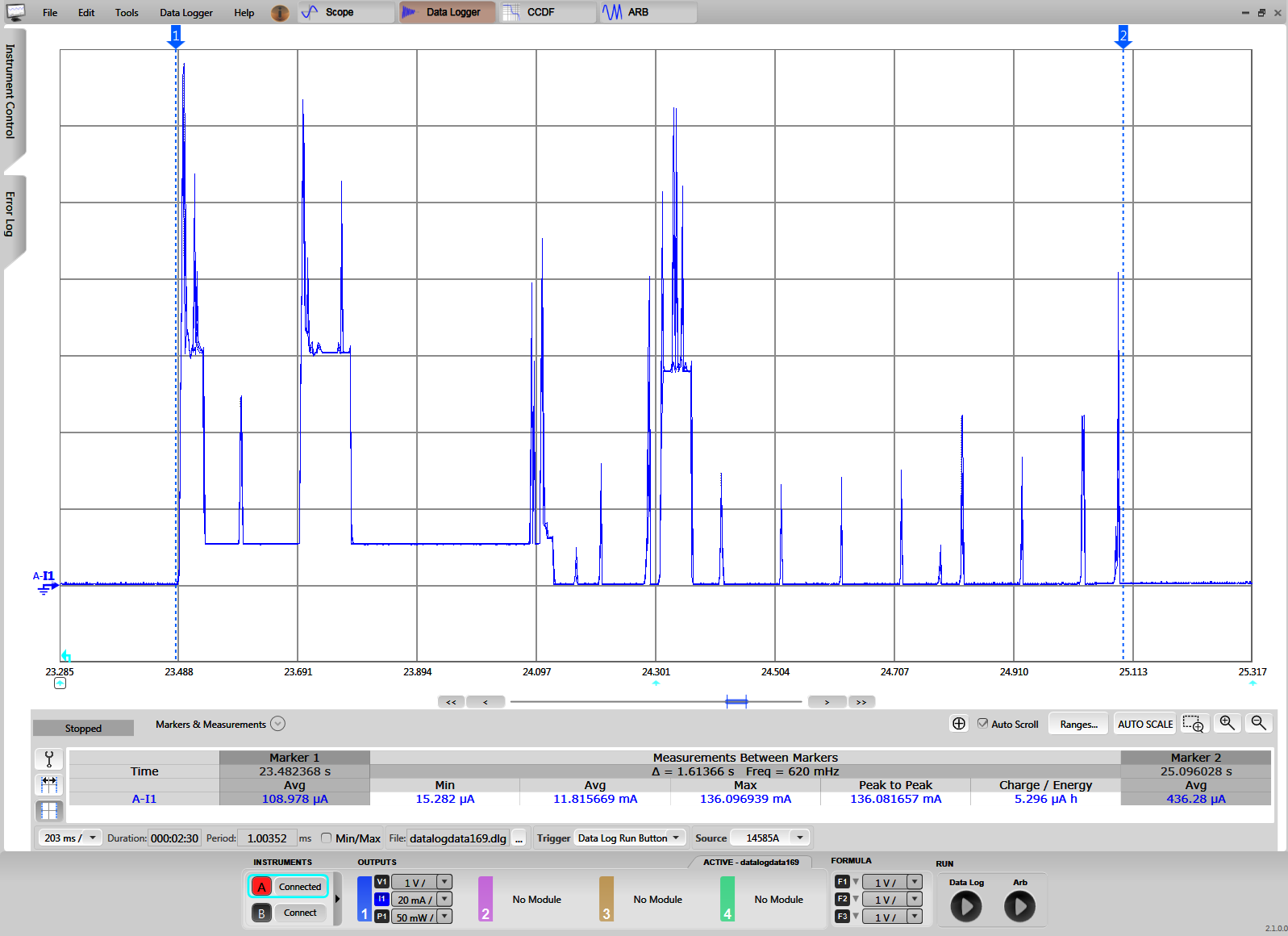 Figure 3-17 CC3220 Current Consumption During Lock Status Request
Similar to the lock or unlock command case, the first spike in current after the cursor represents when the network processor detects a message is ready for it and wakes up to poll the AP. When the message is received, it is passed to the MCU to be parsed. Users can see from Figure 3-17 that the current increases significantly in the middle of the cycle when the lock state is transmitted to the cloud (MQTT broker). After the message is received by the MQTT broker and acknowledged, the system enters the idle connected state. Users can see from Figure 3-17 that the system again waits for a timeout to occur before resuming the configured LSI.
The average current consumed by the CC2640R2F SNP throughout the provisioning process (while advertising, paired, and exchanging AP credentials) was approximately 211.8 µA. While idle (before and after provisioning), the average current consumed by the CC2640R2F was measured to be approximately 40 µA. Figure 3-18 and Figure 3-19 show the current consumption from both measurements.
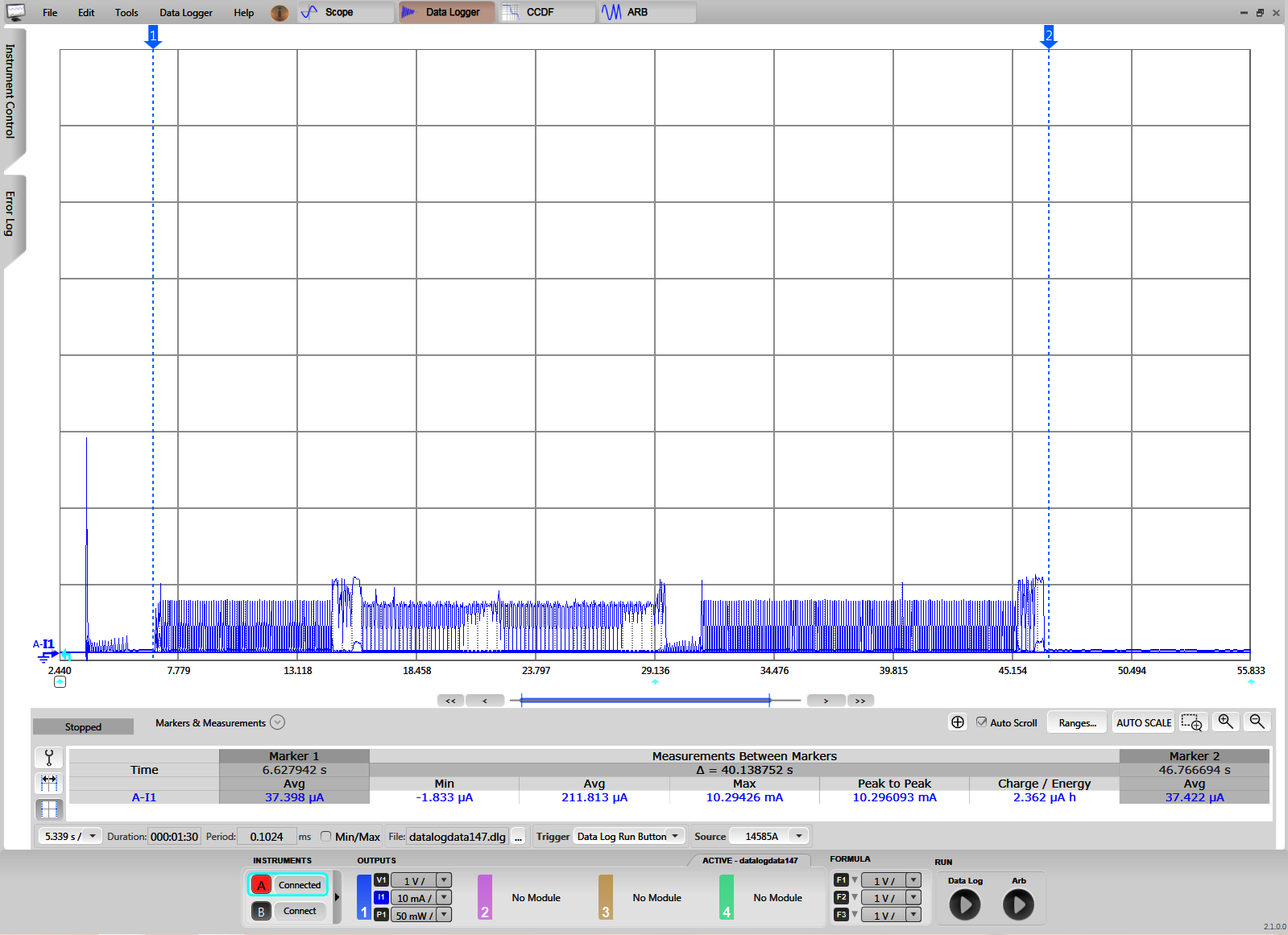 Figure 3-18 CC2640R2F Current Consumption During Provisioning
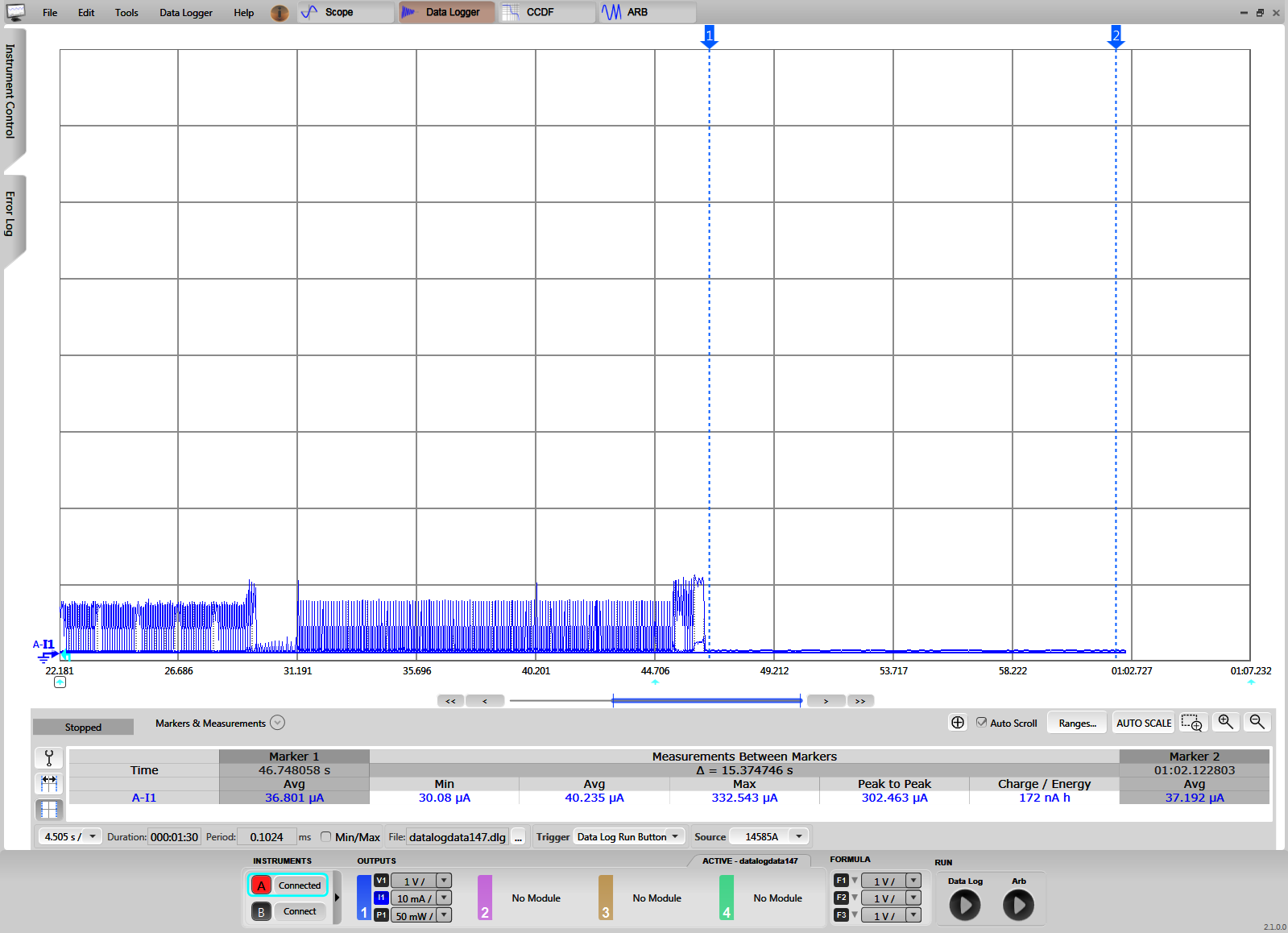 Figure 3-19 CC2640R2F Current Consumption While Idle
The power consumed by the DRV8837 during lock and unlock events was also measured. Specifically, the current consumed while supplying 5 V to the motor power supply of the DRV8337 and driving a load was measured. The load used was a deadbolt installed in a door. The average current consumption while locking and unlocking the deadbolt was approximately 77.6 mA and 73.1 mA, respectively, over the two-second interval that the motor was driven. Figure 3-20 and Figure 3-21 show the current consumption.
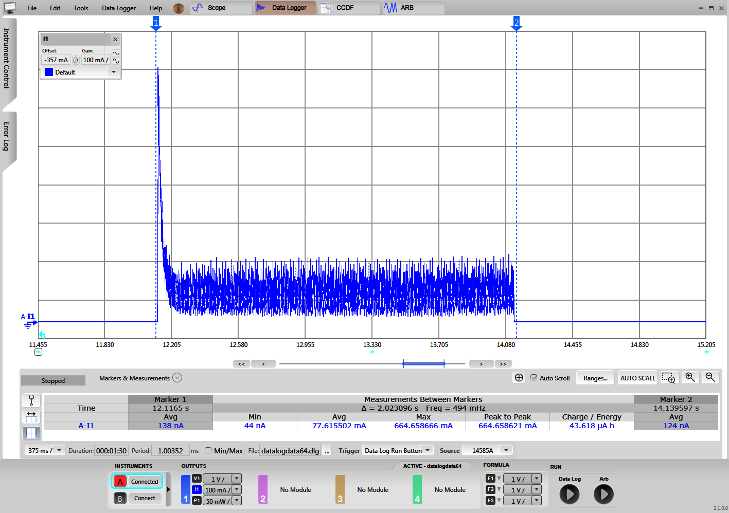 Figure 3-20 DRV8837 Current During Lock Event
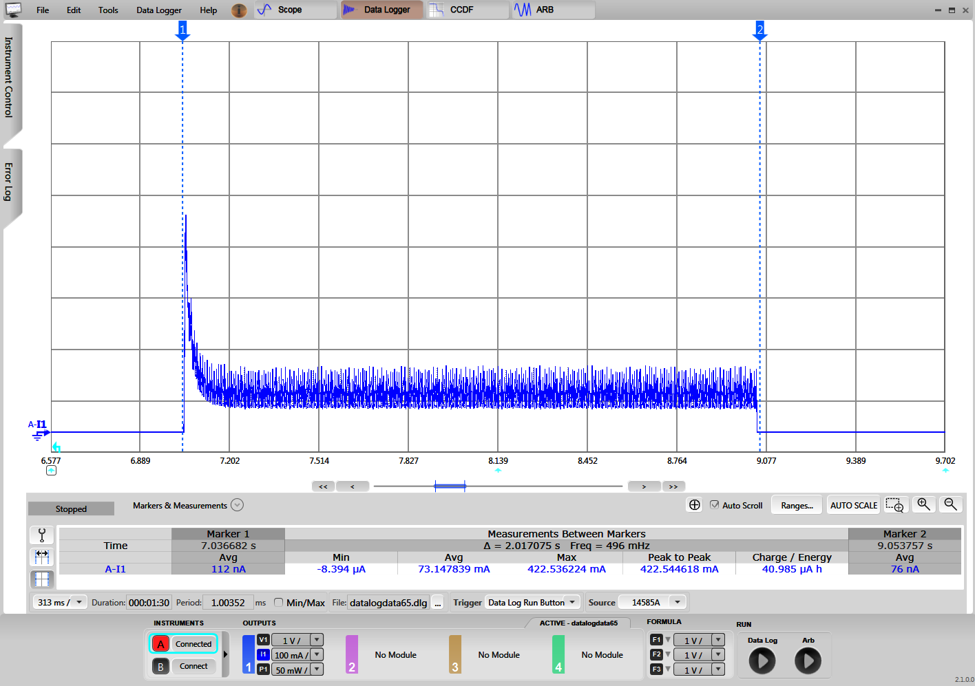 Figure 3-21 DRV8837 Current During Unlock Event
In between lock events, the DRV8837 is held in sleep mode by the CC3220S. The average sleep current of the motor while the DRV8837 was held in sleep was 0.099 µA and Figure 3-22 shows the current measurement.
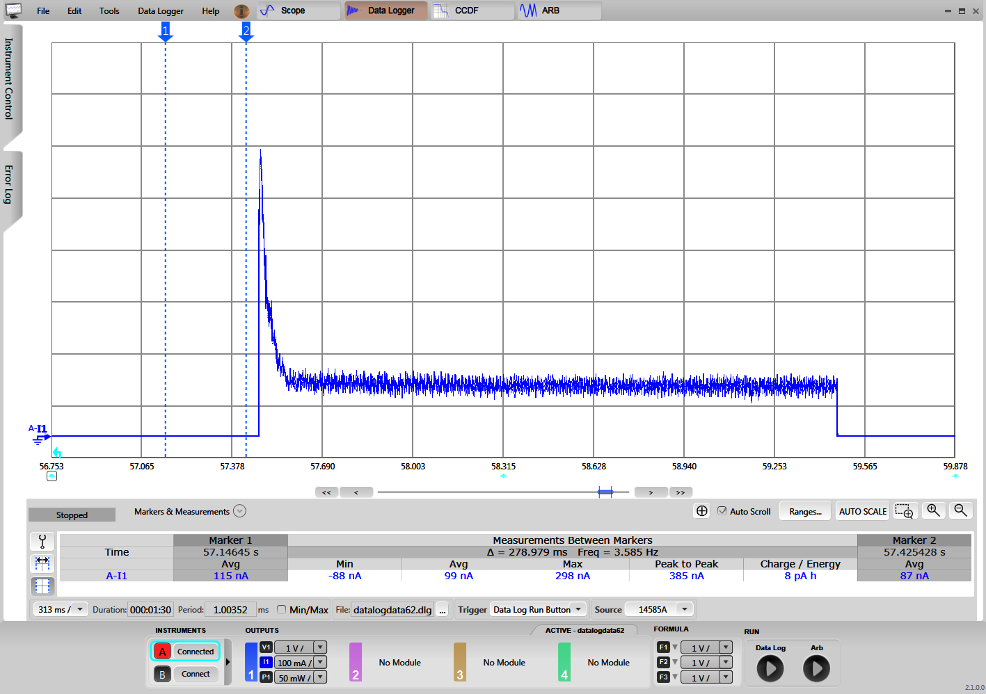 Figure 3-22 DRV8837 Sleep Current
The previously listed results are based on EVMs, not an optimized hardware design. A system with an optimized hardware design may provide improved results.