TIDUE59A May 2018 – September 2020
- Description
- Resources
- Features
- Applications
- 1System Description
-
2System Overview
- 2.1 Block Diagram
- 2.2 Design Considerations
- 2.3 Highlighted Products
- 2.4 System Design Theory
- 3Hardware, Software, Testing Requirements, and Test Results
- 4Design Files
- 5Software Files
- 6Related Documentation
- 7Terminology
- 8About the Author
- 9Revision History
2.4.3 Software Architecture
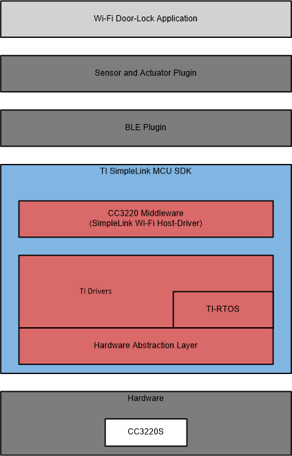
The software provided for the TIDC-01005 is a multithreaded application based on the SimpleLink CC3220 SDK, SimpleLink SDK BLE Plugin, and the Sensor and Actuator Plugin. The TIDC-01005 software uses TI-RTOS to support multithreading and TI-Drivers as the primary interface for managing hardware peripherals (for example, communications peripherals, timers, and digital I/Os). Figure 2-3 shows an overall block diagram for the software.
 Figure 2-3 Wi-Fi, Door-Lock Software Block Diagram
The software for the TIDC-01005 demonstrates multiple features that are supported in a Wi-Fi, electronic, smart-lock design including controlling a motor driver to actuate a lock, reading sensor data, managing a Wi-Fi connection (including provisioning), sending and receiving messages through the cloud, and performing OTA software updates. Each of these features are handled by different software modules in the application, and each module consists of one or more TI-RTOS tasks. In addition to tasks dedicated for each feature, the software includes an overall Wi-Fi door-lock module that is responsible for spawning all other threads and a control module that handles system-level requests such as resets. Dividing the software into separate modules and dedicating independent tasks to each feature helps make the design more modular, so it can be easily modified for different applications.
Table 2-2 lists a description of each software module and the associated source files.
| MODULE | SOURCE FILES | DESCRIPTION |
|---|---|---|
| Wi-Fi Door Lock Application Module | wifi_doorlock_app.h/.c | Starts Wi-Fi door-lock application by initializing system and spawning threads |
| Control Module | control_task.h/.c | Handles system-level requests such as system resets |
| Wi-Fi Connection Management | network_if.h/.c | Connects CC3220 to an AP based on profiles, or handles events to start provisioning |
| Wi-Fi Provisioning | provisioning_task.h/.c | Starts or stops provisioning process and executes state machine to handle provisioning events |
| MQTT Client | mqtt_client_task.h/.c and mqtt_client_cbs.h/.c | Runs MQTT client, receives incoming MQTT messages, publishes MQTT messages to signal device state, and triggers events based on MQTT messages |
| Wi-Fi OTA | cloud_ota_task.h/.c | Runs OTA state machine |
| Motor Control | motor_driver_if.h/.c | Drives motor based on MQTT messages received from the cloud |
| Sensor | bmi160_support.h/.c | Configures and reads sensor data from IMU when enabled |
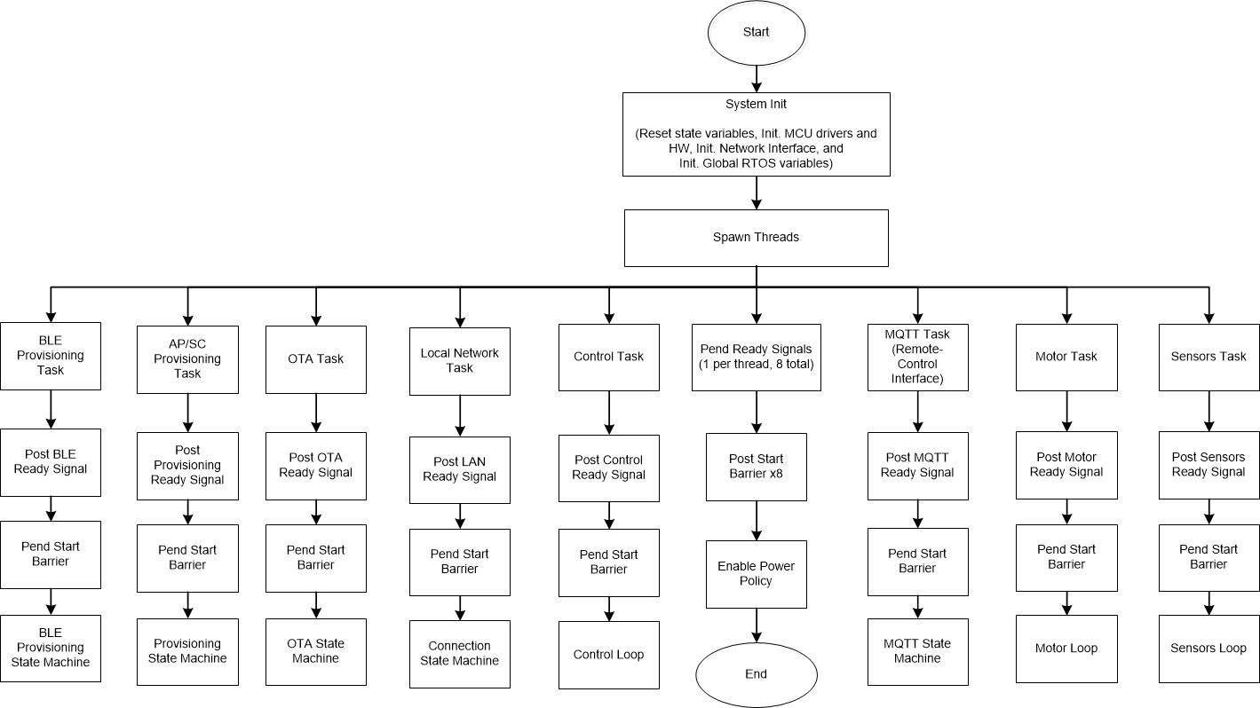
Figure 2-4 shows the overall software flow used to initialize the system and spawn all of the software tasks. The details of each of the spawned tasks are described in the following sections.
 Figure 2-4 Overall Software Flow Diagram