TIDUE59A May 2018 – September 2020
- Description
- Resources
- Features
- Applications
- 1System Description
-
2System Overview
- 2.1 Block Diagram
- 2.2 Design Considerations
- 2.3 Highlighted Products
- 2.4 System Design Theory
- 3Hardware, Software, Testing Requirements, and Test Results
- 4Design Files
- 5Software Files
- 6Related Documentation
- 7Terminology
- 8About the Author
- 9Revision History
3.1.2.3.2.2 Send and Receive Messages (MQTT)
After the RTC is updated to the current network time, the CC3220 connects to an MQTT broker over TLS, using the MQTT library from the SimpleLink SDK. The MQTT library implements a set of functions that can be used to operate as an MQTT client without dependency on connecting to a specific server. In this example, an open eclipse broker (iot.eclipse.org).
For this demo, the CC3220 subscribes to four different topics, as follows:
- /Broker/To/cc32xx/doorLock
- /cc3220/doorLock/<Unique Device ID>/LockStatus
- /cc3220/doorLock/<Unique Device ID>/LockControl
- /cc3220/doorLock/<Unique Device ID>/LockOTA
In the topic names, <Unique Device ID> indicates the 128-bit unique device identifier (in hexadecimal format) built into each CC3220S device. This ID makes the topics used by each device unique, which can prevent devices from receiving messages intended for other systems. The actual topic names used for a specific device are printed at the top of the serial terminal when the application restarts. The application dynamically sets the topic names by reading the device ID from the network processor and printing the ID value to the topic strings before they are used in the application.
Only topics 2, 3, and 4 are currently used by the demo. Topic 2 can be used by a peer device to get the current state of the lock. The CC3220 publishes the state of the lock in JSON format in response to any message received on topic 2. To prevent the device from receiving its response to a status request, a separate topic is used by the device to publish the lock state. The CC3220 publishes the lock state on the topic: /cc3220/doorlock/<Unique Device ID>/LockState.
Table 3-6 lists the format of the JSON message sent on the LockState topic.
| STATE | DATA |
|---|---|
| Locked | {"state": "locked"} |
| Unlocked | {"state": "unlocked"} |
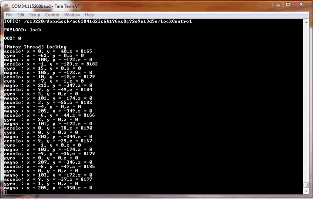
Topic 3 can be used to change the state of the lock (locked or unlocked). For example, to put the demo in the locked state, the user must publish the message lock to topic 3. To put the demo in the unlocked state, the user must publish the message unlock to topic 3. Depending on which command is received on topic 3, the motor spins clockwise or counter-clockwise. When running the demo while connected to a serial terminal, the received command is printed to the screen along with the sensor data read while driving the motor.
Figure 3-11 shows an example of what is shown in the serial terminal.
 Figure 3-11 Debug Print When Lock Message Sent on LockControl Topic
Topic 4 is used to signal to the device to initiate an OTA update. When the device receives any message published on topic 4, the OTA state machine runs. For a detailed description of the OTA implementation, see the Section 2.4.7 of this document.
Any time the CC3220 receives a message on a topic that it is subscribed to or publishes to the Lock State topic, the device prints a debug message to the serial terminal. This feature can be used to monitor the system response while debugging. Any MQTT client that can connect to the Eclipse IoT broker can be used to test out the functionality of the demo using the topic names shown here. For example, the mobile applications mentioned in the Wi-Fi MQTT SimpleLink Academy Training can be used to test the behavior of a remote client that can control and monitor the state of the demo.
Establishing the MQTT connection over TLS is facilitated by the use of the secure MQTT port (8883) and includes the Root CA for the eclipse server, to enable the CC3220 to validate the server certificate chain. The Eclipse server Root CA must be added to the CC3220S file system before running the demo (already included in the provided UniFlash bundle). In the application, the path to this file on the file system and the secure MQTT port are specified in the MQTT client context struct when SECURE_CLIENT is defined at the top of wifi_doorlock_app.c.
Due to the fact that the software provided is a demo built to be used with a preconfigured broker, there are some limitations to the implementation. Mutual authentication is not supported by the demo, because there is no mechanism configured for the Eclipse broker to identify the CC3220S device. Mutual authentication can be added by the user when using an actual server for production. The demo also skips the domain name verification step and disables the option to verify the server root CA name in the certificate catalog. The certificate catalog verification step must be disabled when using the certificate playground during development, because it does not include all of the actual trusted root certificate authorities. For a production system, the production certificate catalog must be used and TI recommends enabling both certificate catalog verification and domain name verification.
The root CA for the Eclipse broker will expire over time. The user must ensure the certificate loaded onto the CC3220S serial flash is the most recent root CA or the connection to the broker may fail.