TIDUE59A May   2018  – September 2020


  1.   Description
  2.   Resources
  3.   Features
  4.   Applications
  5. 1System Description
    1. 1.1 Key System Specifications
  6. 2System Overview
    1. 2.1 Block Diagram
    2. 2.2 Design Considerations
    3. 2.3 Highlighted Products
      1. 2.3.1 CC3220
      2. 2.3.2 CC2640R2F
      3. 2.3.3 DRV8837
    4. 2.4 System Design Theory
      1. 2.4.1 CC3220S to CC2640R2F Interface
      2. 2.4.2 CC3220S to DRV8837 Interface
      3. 2.4.3 Software Architecture
      4. 2.4.4 Network Connection Management
      5. 2.4.5 Provisioning
        1. 2.4.5.1 AP Provisioning and SmartConfig™
        2. 2.4.5.2 Wi-Fi Provisioning Over BLE
      6. 2.4.6 Sending and Receiving Messages Through Cloud
        1. 2.4.6.1 Message Queue Telemetry Transport Protocol
        2. 2.4.6.2 MQTT Client Implementation
      7. 2.4.7 Over-the-Air Updates
        1. 2.4.7.1 HyperText Transfer Protocol
      8. 2.4.8 Security Enablers
        1. 2.4.8.1 Secure Boot
        2. 2.4.8.2 Secure Sockets
          1. 2.4.8.2.1 Hardware Accelerators
          2. 2.4.8.2.2 Simple Network Time Protocol
        3. 2.4.8.3 File System Security
          1. 2.4.8.3.1 Failsafe Files and Bundle Protection
      9. 2.4.9 Low-Power Consumption
  7. 3Hardware, Software, Testing Requirements, and Test Results
    1. 3.1 Required Hardware and Software
      1. 3.1.1 Hardware
        1. 3.1.1.1 CC3220S LaunchPad™ Development Kit
        2. 3.1.1.2 CC2640R2F LaunchPad™ Development Kit
        3. 3.1.1.3 Sensor BoosterPack™ Connections (BMI160)
        4. 3.1.1.4 DRV8837EVM Modifications and Connections
        5. 3.1.1.5 Assembling EVMs
      2. 3.1.2 Software
        1. 3.1.2.1 Getting Started With Software
          1. 3.1.2.1.1 Build simple_np Application and Flash CC2640R2F
          2. 3.1.2.1.2 Use Premade UniFlash ImageCreator Project
          3. 3.1.2.1.3 Importing Project Source Files Into CCS
        2. 3.1.2.2 User Files
        3. 3.1.2.3 Run Wi-Fi® Doorlock Demo
          1. 3.1.2.3.1 Connect CC3220 to Network
          2. 3.1.2.3.2 Networking Functions
            1. 3.1.2.3.2.1 Get Current Date and Time (SNTP)
            2. 3.1.2.3.2.2 Send and Receive Messages (MQTT)
            3. 3.1.2.3.2.3 Perform Software Update Using Dropbox (OTA Update)
    2. 3.2 Testing and Results
      1. 3.2.1 Pass or Fail Tests
      2. 3.2.2 Power Measurements
      3. 3.2.3 Test Setup
        1. 3.2.3.1 CC3220S
        2. 3.2.3.2 CC2640R2F
        3. 3.2.3.3 DRV8837
      4. 3.2.4 Test Results
      5. 3.2.5 Battery Life Estimate
  8. 4Design Files
  9. 5Software Files
  10. 6Related Documentation
    1. 6.1 Trademarks
  11. 7Terminology
  12. 8About the Author
  13. 9Revision History

CC2640R2F LaunchPad™ Development Kit

All jumpers must be removed from the CC2640R2F LaunchPad kit before connecting it to the CC3220S LaunchPad kit to run the demo. However, the steps for programming the LAUNCHXL-CC2640R2 described in Section 3.1.2 must be completed before removing all jumpers and assembling the hardware. Figure 3-2 shows the LAUNCHXL-CC2640R2 when programmed.
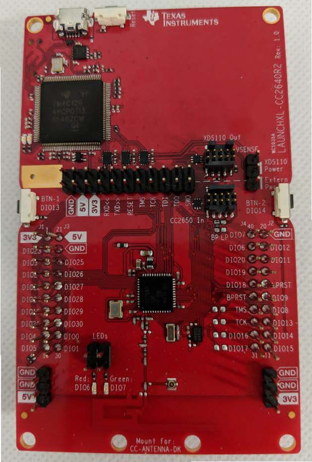
GUID-92CFCE34-DDB2-4307-91D8-B31F6083A28A-low.jpg Figure 3-2 CC2640R2F LaunchPad Kit Configuration

The default pin mapping of the SNP images for the CC2640R2F, provided in the BLE plugin, lead to pin conflicts with the CC3220S LaunchPad kit and the sensor BoosterPack plugin module. To allow all three EVMs to be connected together with minimal hardware modifications, the user must rebuild the SNP application (simple_np) from the SimpleLink CC2640R2F SDK, with an updated pin mapping before programming the board. The process for updating the pin mapping of the CC2640R2F is described in Section 3.1.2, but it results in the following connections between the CC3220S and the CC2640R2F (see Table 3-1).

Table 3-1 CC3220S and CC2640R2F Pin Mapping
CC3220S CC2640R2F
Pin 3 (UART0 TX) DIO 2 (UART RX)
Pin 4 (UART0 RX) DIO 3 (UART TX)
Pin 62 (MRDY) DIO 21 (MRDY)
Pin 8 (SRDY) DIO 11 (SRDY)
Pin 7 (RESET) BPRST (RESET)

All of the pins listed in Table 3-1 are connected when stacking the LaunchPads to assemble the demo, except for the RESET line. A single, 2-pin jumper can be used to connect Pin 7 of the CC3220S to the BPRST pin of the CC2640R2F when the LaunchPad kits and BoosterPack module are stacked, as described in Section 3.1.1.5.