SPNA241 August 2019 RM41L232 , RM42L432 , RM44L520 , RM44L920 , RM46L430 , RM46L440 , RM46L450 , RM46L830 , RM46L840 , RM46L850 , RM46L852 , RM48L530 , RM48L540 , RM48L730 , RM48L740 , RM48L940 , RM48L950 , RM48L952 , RM57L843 , TMS570LC4357 , TMS570LC4357-EP , TMS570LC4357-SEP , TMS570LS0232 , TMS570LS0332 , TMS570LS0432 , TMS570LS0714 , TMS570LS0714-S , TMS570LS0914 , TMS570LS10106 , TMS570LS10206 , TMS570LS1114 , TMS570LS1115 , TMS570LS1224 , TMS570LS1225 , TMS570LS1227 , TMS570LS20206 , TMS570LS20206-EP , TMS570LS20216 , TMS570LS20216-EP , TMS570LS2124 , TMS570LS2125 , TMS570LS2134 , TMS570LS2135 , TMS570LS2135-S , TMS570LS3134 , TMS570LS3135 , TMS570LS3137 , TMS570LS3137-EP
-
CAN Bus Bootloader for Hercules Microcontrollers
- Trademarks
- 1 Introduction
- 2 Hardware Requirements
- 3 CAN Settings
- 4 Software Coding and Compilation
- 5 Exception Vector Table
- 6 ECC Generation for Bootloader Code
- 7 ECC Generation for Application Code
- 8 During Bootloader Execution
- 9 Bootloader Flow
- 10 CAN Bootloader Operation
- 11 CAN Bootloader Protocol
- 12 Create Application for Use With the Bootloader
- 13 Sample Code for PC-Side Application
- 14 References
10 CAN Bootloader Operation
- Load the bootloader to Flash.
- Load the user application code.
- User application is downloaded and programmed. To execute the new application, the bootloader host sends REET command or RUN command to the bootloader.
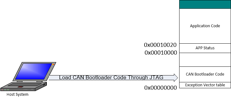
The CAN bootloader is built with Code Composer Studio 9.x and loaded through the JTAG port into the lower part of the program Flash memory at 0x00000000.
 Figure 7. The CAN Bootloader is Loaded Through the JTAG Port
 After HDK reset, F021 Flash APIs, Flash API related code and variables are copied from Flash to SRAM, and execute the bootloader in Flash.
First, it checks to see if the GPIO_A7 pin is pulled low by calling CheckForceUpdate(). If GPIO-A7 is pulled LOW, the application code is forced to be updated. The GPIO pin check can be enabled with ENABLE_UPDATE_CHECK in the bl_config.h header file, in which case an update can be forced by changing the state of a GPIO pin (with the push button S1 on HDK ).
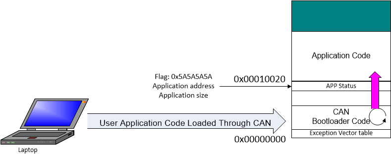
Then, it checks the magic word or flag at 0x00010000. If the flag is a valid number (0x5A5A5A5A), the bootloader jumps to the application code at 0x00010020. If the flag is not the valid number, it configures CAN and SCI, then starts to update the application code by calling UpdaterCan(). After all of the application code is programmed successfully, the application header is programmed to 0x10000. The application header consists of three 32bit words that start at 0x10000 in this example. The first word of the header is the application start address, and the second word is the application size, and third word is the status flag. If the application is programmed sucessfully, the flag is 0x5A5A5A5A..
The CAN bootloader uses Message Box 2 to handle incoming messages; Message Box 1 is used for handling the outgoing messages.
 Figure 8. User Application Code is Loaded Through the CAN Bootloader