SWRU553A September 2019 – February 2020
-
AWRx Cascaded Radar RF Evaluation Module (MMWCAS-RF-EVM)
- Trademarks
- 1 Getting Started
- 2 Hardware Description
- 3 Design Files and Software Tools
- 4 PCB Dimensions and Mounting Information
- 5 PCB Storage and Handling Recommendations
- 6 References
- 7 Regulatory Information
- Revision History
1.1 Introduction
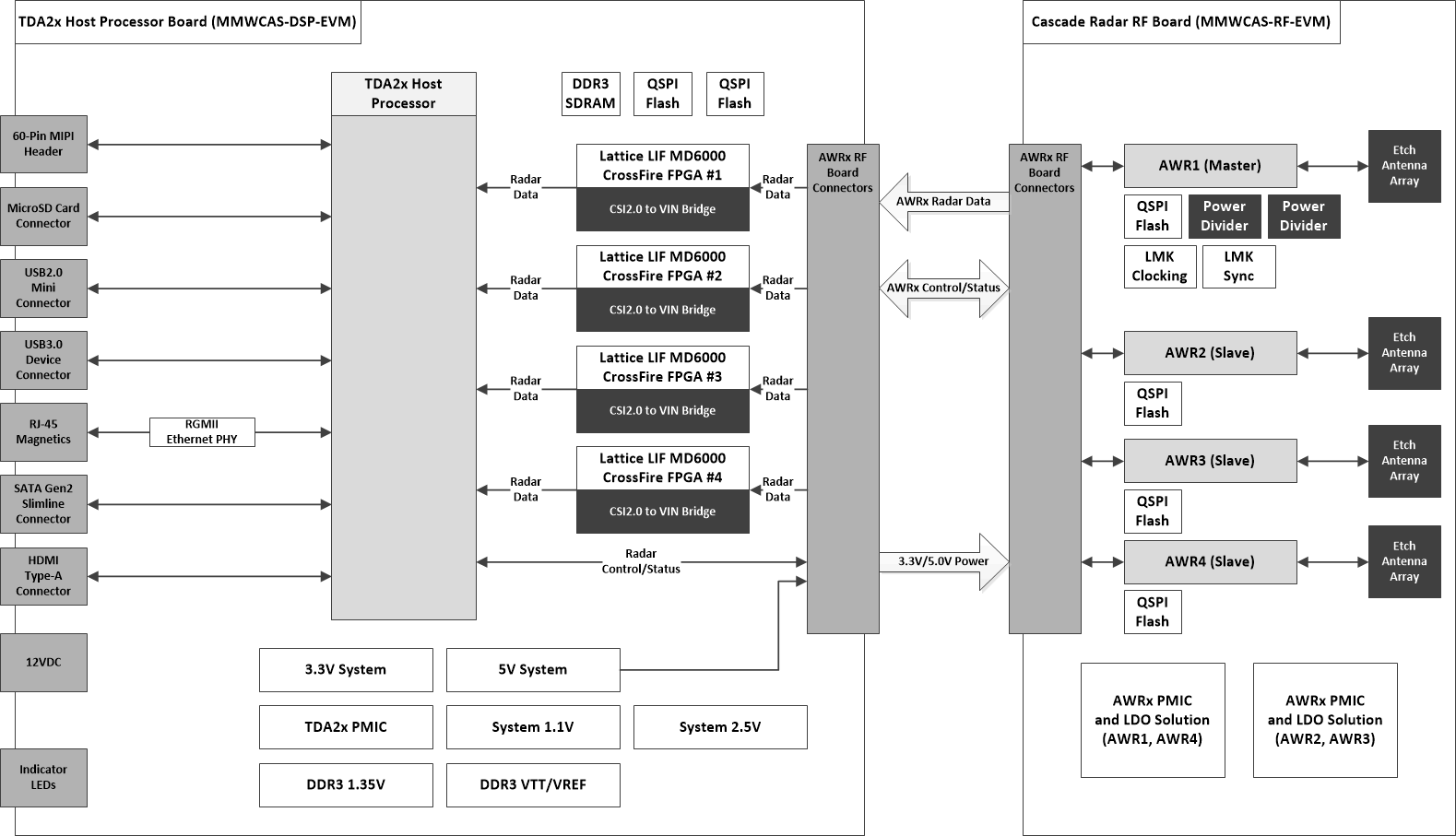
The AWRx Cascaded Radar RF evaluation board is an AWRx based mmWave sensing solution from TI implementing a 4-device, cascaded, array of AWRx mmWave devices. In this cascaded radar configuration, a single master device distributes a 20 GHz LO signal between all 4 devices, allowing these 4 devices to operate as a single RF transceiver. This enables support for up to 12 TX and 16 RX antenna elements. In TX beam-forming, beam-steering and MIMO/SIMO use-cases the larger number of antenna elements allows for higher SNR and higher angular resolution compared to a single-device system.
The Cascade Radar evaluation board interfaces to a companion TI TDA2x based Host/Data Capture board that is responsible for controlling the AWRx devices and receiving captured IF ADC samples. The TI TDA2x Host/Data Capture board includes SSD storage for supporting longer term data capture scenarios and 1Gigabit Ethernet connectivity for control and offloading captured data.
 Figure 1. Cascade RF EVM and companion TDA2x Host Processor Board Block Diagram
 The Cascade Radar evaluation board, when combined with a compatible host/data capture board, contains everything needed to start evaluating a single-device, or 2-device, 3-device or 4-device cascaded radar solution.