SPRUIQ4 May 2019 TMS320F280021 , TMS320F280021-Q1 , TMS320F280023 , TMS320F280023-Q1 , TMS320F280023C , TMS320F280025 , TMS320F280025-Q1 , TMS320F280025C , TMS320F280025C-Q1 , TMS320F280040-Q1 , TMS320F280040C-Q1 , TMS320F280041 , TMS320F280041-Q1 , TMS320F280041C , TMS320F280041C-Q1 , TMS320F280045 , TMS320F280048-Q1 , TMS320F280048C-Q1 , TMS320F280049 , TMS320F280049-Q1 , TMS320F280049C , TMS320F280049C-Q1 , TMS320F28374D , TMS320F28374S , TMS320F28375D , TMS320F28375S , TMS320F28375S-Q1 , TMS320F28376D , TMS320F28376S , TMS320F28377D , TMS320F28377D-EP , TMS320F28377D-Q1 , TMS320F28377S , TMS320F28377S-Q1 , TMS320F28378D , TMS320F28378S , TMS320F28379D , TMS320F28379D-Q1 , TMS320F28379S
- Introduction
- 1Getting Familiar With the Kit
-
2Hardware Overview
- 2.1 IDDK Evaluation Board
- 2.2 Functional Blocks
- 2.3 Processor Section
- 2.4 Control Processor Slot – H1
- 2.5 Expansion Processor Slots
- 2.6 Position Encoder Suite
- 2.7 Current Sensor Suite
- 2.8 Power Supplies and GND Plane Configurations
- 2.9 Rectifier and Inverter
- 2.10 DACs
- 2.11 Power Stage Disable Circuits
- 3Hardware Resource Mapping
2.2 Functional Blocks
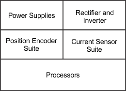
Figure 2-2 shows the functional block diagram of the IDDK. Dedicated processors provide the system with control, real-time connectivity, and safety functions. The control processor has a suite of position encoder interfaces and current sense interfaces. You can configure the controller to select the interfaces you want. Table 2-1 shows that each block is subdivided into macros representing a subfunction.
 Figure 2-2 Functional Block Diagram of IDDK
 Table 2-1 Hardware Macros in IDDK and Their Functions
| Functional Block | Macro Reference | Macro Function |
|---|---|---|
| Power Supplies | M2 | Isolated DC-DC converter – 400 V to 15 V |
| M3 | DC-Power Supply – Linear Reg 15 V – 5 V to 3.3 V | |
| M8 | Isolated DC/DC Converter – 400 V to 15 V | |
| M9 | DC-Power Supply – Linear Reg 15 V – 5 V to 3.3 V | |
| Rectifier and Inverter | M1 | AC Main Power Entry |
| M4 | 3-Phase Inverter | |
| Current Sensor Suite | M5 | Flux Gate – Motor Current Sense Interface |
| M6 | Overcurrent Protection | |
| M7 | Sigma-Delta – Motor Current Sense Interface | |
| Position Encoder Suite | M10 | QEP Interface |
| M11 | Resolver Interface | |
| M12 | EnDat Encoder Interface | |
| M13 | Sin-Cos Encoder Interface | |
| Processors | Main board | All other functions |
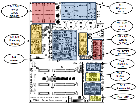
The following sections present each functional block and their macros. Figure 2-3 shows the layout of various macros in the board. Schematic details of the individual macros are available at \ti\c2000\C2000Ware_MotorControl_SDK_version\solutions\tmdxiddk379d\hardware\IDDK_HwDevPkg_r2.2.1.
 Figure 2-3 Layout of IDDK EVM With Functional Macros