SPRUIK4A September 2018 – June 2019 TMS320F280021 , TMS320F280021-Q1 , TMS320F280023 , TMS320F280023-Q1 , TMS320F280023C , TMS320F280025 , TMS320F280025-Q1 , TMS320F280025C , TMS320F280025C-Q1 , TMS320F280040-Q1 , TMS320F280040C-Q1 , TMS320F280041 , TMS320F280041-Q1 , TMS320F280041C , TMS320F280041C-Q1 , TMS320F280045 , TMS320F280048-Q1 , TMS320F280048C-Q1 , TMS320F280049 , TMS320F280049-Q1 , TMS320F280049C , TMS320F280049C-Q1 , TMS320F28075 , TMS320F28075-Q1 , TMS320F28076 , TMS320F28374D , TMS320F28374S , TMS320F28375D , TMS320F28375S , TMS320F28375S-Q1 , TMS320F28376D , TMS320F28376S , TMS320F28377D , TMS320F28377D-Q1 , TMS320F28377S , TMS320F28377S-Q1 , TMS320F28378D , TMS320F28378S , TMS320F28379D , TMS320F28379D-Q1 , TMS320F28379S
-
C2000 Software Frequency Response Analyzer (SFRA) Library and Compensation Designer in SDK Framework
- Trademarks
- 1 Introduction
- 2 Installing the SFRA Library
- 3 Module Summary
- 4 Compensation Designer
- 5 Case Study
- 6 Running Software Test Bench Example for SFRA
- 7 Using SFRA Without SFRA GUI Integration
- 8 FAQ
- Revision History
4.2 Compensation Style and Number
Different styles of compensation are supported by the Compensation Designer and are listed in Table 4.
Table 4. Different Compensation Style Supported by Compensation Designer
| Style | Description | Implementation |
|---|---|---|
| Proportional Gain | Proportional gain controller | Simple multiply in control software |
| Series PI | Series proportional integrgral controller tuned with pole zero format | DCL_PI_C1/C2 or similar |
| Parallel PI | Parallel proportional integrgral controller tuned with pole zero format | DCL_PI_C3/C4 or similar |
| Two Pole Two Zero | Two pole two zero compensator | DCL_DF22 or similar |
| One Pole One Zero Lead Lag Compensator | Lead Lag compensator implemented using one pole one zero | DCL_DF11 or DCL_DF22 or similar |
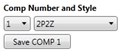
The standalone GUI when ran from the SFRA install folder enables designing up to ten compensators each of which can be tuned using any of the different compensation styles. The Compensation Style and Number can be selected using the drop down box.
Any changes to the compensation value are not saved until the button “Save COMP<number> is selected (see Figure 9). This prevents any inadvertent change to the compensation values.
 Figure 9. Compensation Number and Style Selection
 Depending on which compensation style is selected, different panels on the GUI will become active. The coefficients for the DCL module based on the compensation style and the values entered in the tuning window are displayed on the GUI and can be copied into the user code.
NOTE
Assuming Fs is the control loop frequency or the rate at which the control loop is executed and T=1/Fs.