SPRAD28 October 2022 AM2431 , AM2432 , AM2434 , AM2631 , AM2631-Q1 , AM2632 , AM2632-Q1 , AM2634 , AM2634-Q1 , AM263P2-Q1 , AM263P4 , AM263P4-Q1 , AM26C31-EP , AM26C31M , AM26C32-EP , AM26C32C , AM26C32M , AM26LS31M , AM26LS32AM , AM26LS33A-SP , AM26LS33AM , AM26LV31E-EP , AM26LV32E-EP , AM26S10 , AM2732 , AM2732-Q1
- Abstract
- Trademarks
- 1 Building for Debug
- 2 Code Composer Studio Stop-Mode Debugging
- 3 Debug Logging
- 4 Multi-Core Debug
- 5 Debugging Arm Cortex-R5 Exceptions
- 6 Debugging Arm Cortex-M4 Exceptions
- 7 Debugging Memory
- 8 Debugging Boot
- 9 Debugging Real-Time Control Loops
- 10E2E Support Forums
5.2 Aborts
When an abort happens, the program gets halted at the Exception Vector Table in address 0xFFFF00##:
| Value of V bit | Exception vector base location |
|---|---|
| 0 | 0x00000000 |
| 1 (HIVECS) | 0xFFFF0000 |
The last two nibbles in the address (0xFFFF00##) indicates the type of abort as shown.
| Exception | Offset From Vector Base |
|---|---|
| Reset | 0x00 |
| Undefined Instruction | 0x04 |
| Software Interrupt | 0x08 |
| Abort (prefetch) | 0x0C |
| Abort (data) | 0x10 |
| IRQ | 0x18 |
| FIQ | 0x1C |
All exceptions end up in the address specified in the Exception Vector Table. The program execution can then branch to application-specific handlers. The branch target address differs based on the application. Two such examples are discussed below:
- An application can use the default exception handlers designed as a “trap” where the execution gets stuck. Below is an example to a prefetch abort handler (an infinte loop):
Void __attribute__((interrupt("ABORT"), section(".text.hwi"))) HWiP_prefetch_abort_handler(void)
{
   volatile uint32_t loop = 1;
   while(loop)
      ;
}- An implementation can have advanced exception handling capabilities in the OS, where the details of the exception will be read and a corresponding error code are notified by the custom OS error handler. In such cases, details of the error codes can be checked to understand the actual exception that was triggered. R13, R14, and SPSR registers of the corresponding exception can be read for debugging the issue.
There are three important Arm Cortex-R5 registers that can also be used to confirm the current state of the processor.
CPSR:
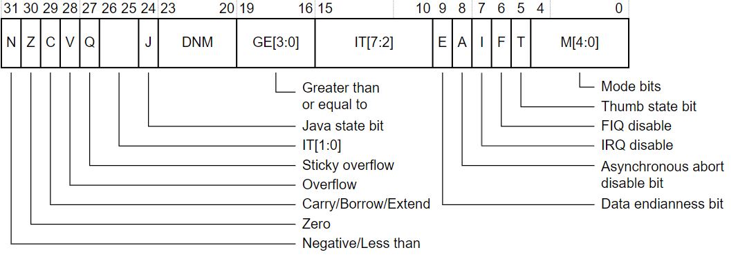
The CPSR can be used to verify the current mode of the processor. The mode bits of the CPSR register can be used to check if the current mode is Abort:
| M[4:0] | Mode |
|---|---|
| 10000 | User |
| 10001 | FIQ |
| 10010 | IRQ |
| 10011 | Supervisor |
| 10111 | Abort |
| 11011 | Undefined |
| 11111 | System |
SPSR:
The SPSR can be used to check the previous mode just before entering the exception. For example, if the processor moves from System to Abort Mode, SPSR shows the mode as “System” while CPSR shows the mode as “Abort”. The bit definitions of SPSR register are the same as that of the CPSR register.
R14 Register (Link Register):
The R14 register is used to find the actual instruction or function call that caused the synchronous abort. The actual address of the instruction that triggered the Exception is R14 - x, where “x” depends on the type of exception.
Aborts are usually unintended exceptions resulting due to invalid or unsuccessful access of memory. Some of the causes for aborts are as follows.
- Permission fault indicated by the Memory Protection Unit (MPU)
- Error detected in the data by the ECC checking logic
If the exception is confirmed to be a Data Abort, as the first step check the value of the Data Fault Status Register (DFSR) of the Cortex-R CPU. The DFSR holds status information about the last data fault.
Figure 5-1 shows the DFSR register bit assignments.
 Figure 5-1 DFSR bits
Use the “S” Bit [10] and “Status Bits” [0:3] to understand the nature of the Data Abort. For status description, see Table 5-1.
| Priority | Sources | FSR[10,3:0] | FAR |
|---|---|---|---|
| Highest | Alignment | 0b00001 | Valid |
| Background | 0b00000 | Valid | |
| Permission | 0b01101 | Valid | |
| Synchronous external abort | 0b01000 | Valid | |
| Asynchronous external abort | 0b10110 | Unpredictable | |
| Synchronous parity or ECC error | 0b11001 | Valid | |
| Asynchronous parity or ECC error | 0b11000 | Unpredictable | |
| Debug event | 0b00010 | Unpredictable |
SD Bit:
The SD Bit distinguishes between an AXI Decode or Slave error on an external abort. This bit is valid only for external aborts. For all other types of abort, this bit is set to zero.
- 0 = AXI Decode error (DECERR) or AHB error caused the abort, generated, typically by an interconnect component, to indicate that there is no slave at the transaction address (The address you requested is not valid)
- 1 = AXI Slave error (SLVERR) or unsupported exclusive access caused the abort. Used when the access has reached the slave successfully, but the slave wishes to return an error condition to the originating master an error condition to the originating master. (Valid address, but slave is unable to do the requested operation)
RW Bit:
The RW bit indicates whether a read or write access caused the abort.
- 0 = read access caused the abort
- 1 = write access caused the abort