SNLU232A August 2018 – May 2019
-
1DS90UH949A-Q1EVM or DS90UB949A-Q1EVM User's Guide
- 1.1 General Description
- 1.2 Features
- 1.3 System Requirements
- 1.4 Contents of the Demo Evaluation Kit
- 1.5 Applications Diagram
- 1.6 Typical Configuration
- 1.7 Quick Start Guide
- 1.8 Default Jumper Settings
- 1.9 Default Switch Settings
- 1.10 Demo Board Connections
- 1.11
ALP Software Setup
- 1.11.1 System Requirements
- 1.11.2 Download Contents
- 1.11.3 Installation of the ALP Software
- 1.11.4 Start-Up - Software Description
- 1.11.5 Information Tab
- 1.11.6 HDMI Tab
- 1.11.7 Pattern Generator Tab
- 1.11.8 Registers Tab
- 1.11.9 Registers Tab - Address 0x00 Selected
- 1.11.10 Registers Tab - Address 0x00 Expanded
- 1.11.11 Scripting Tab
- 1.12 Troubleshooting ALP Software
- 1.13 Typical Connection and Test Equipment
- 1.14 Equipment References
- 1.15 Cable References
- 2Bill of Materials
1.13 Typical Connection and Test Equipment
The following is a list of typical test equipment that may be used to generate signals for the serializer inputs:
- Digital Video Source – for generation of specific display timing such as Digital Video Processor or Graphics Controller (GPU) with HDMI or OpenLDI output.
- Any other signal generator / video source - This video generator may be used for video signal sources for DVI or DP++
- Any other signal / video generator that provides the correct input levels as specified in the datasheet.
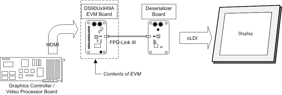
Figure 1-22 shows a typical test set up using a Graphics Controller and display.
 Figure 1-22 Typical Test Setup for Video Application
 Figure 1-23 shows a typical test set up using a video generator and logic analyzer.
 Figure 1-23 Typical Test Setup for Evaluation