SNLU232A August 2018 – May 2019
-
1DS90UH949A-Q1EVM or DS90UB949A-Q1EVM User's Guide
- 1.1 General Description
- 1.2 Features
- 1.3 System Requirements
- 1.4 Contents of the Demo Evaluation Kit
- 1.5 Applications Diagram
- 1.6 Typical Configuration
- 1.7 Quick Start Guide
- 1.8 Default Jumper Settings
- 1.9 Default Switch Settings
- 1.10 Demo Board Connections
- 1.11
ALP Software Setup
- 1.11.1 System Requirements
- 1.11.2 Download Contents
- 1.11.3 Installation of the ALP Software
- 1.11.4 Start-Up - Software Description
- 1.11.5 Information Tab
- 1.11.6 HDMI Tab
- 1.11.7 Pattern Generator Tab
- 1.11.8 Registers Tab
- 1.11.9 Registers Tab - Address 0x00 Selected
- 1.11.10 Registers Tab - Address 0x00 Expanded
- 1.11.11 Scripting Tab
- 1.12 Troubleshooting ALP Software
- 1.13 Typical Connection and Test Equipment
- 1.14 Equipment References
- 1.15 Cable References
- 2Bill of Materials
A EVM PCB Schematics
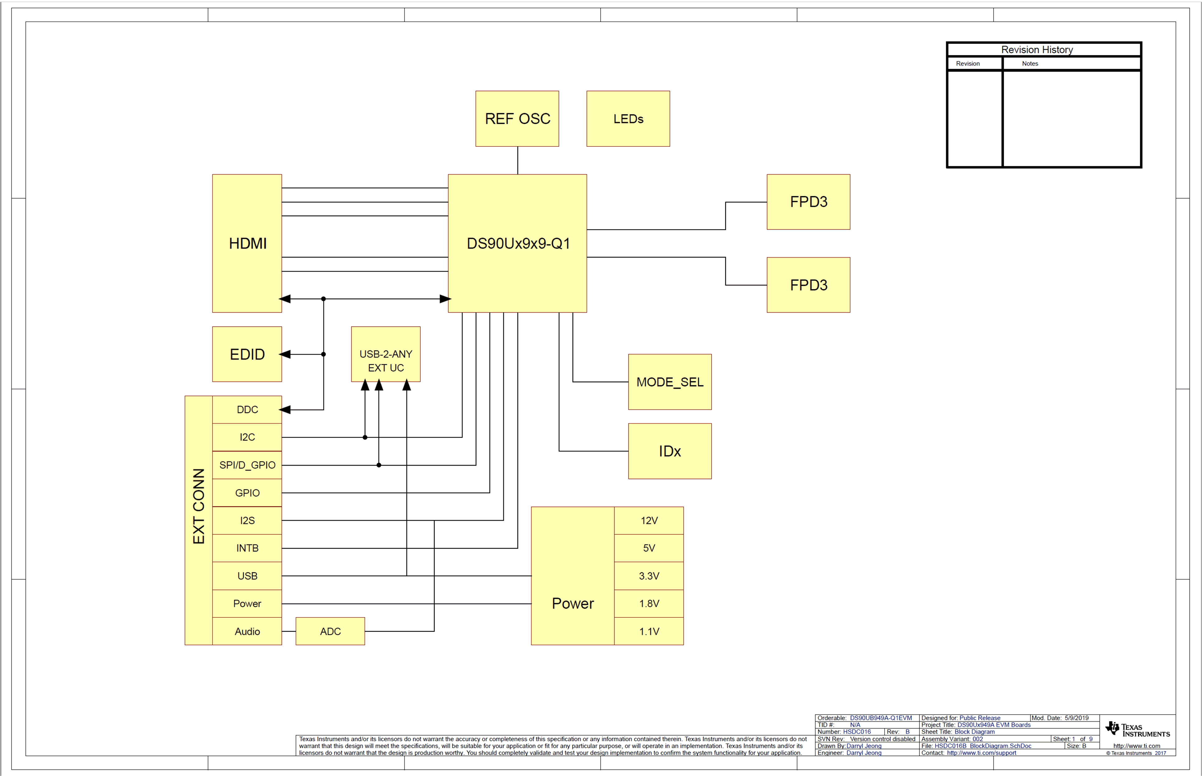 Figure A-1 Schematic - Block Diagram
 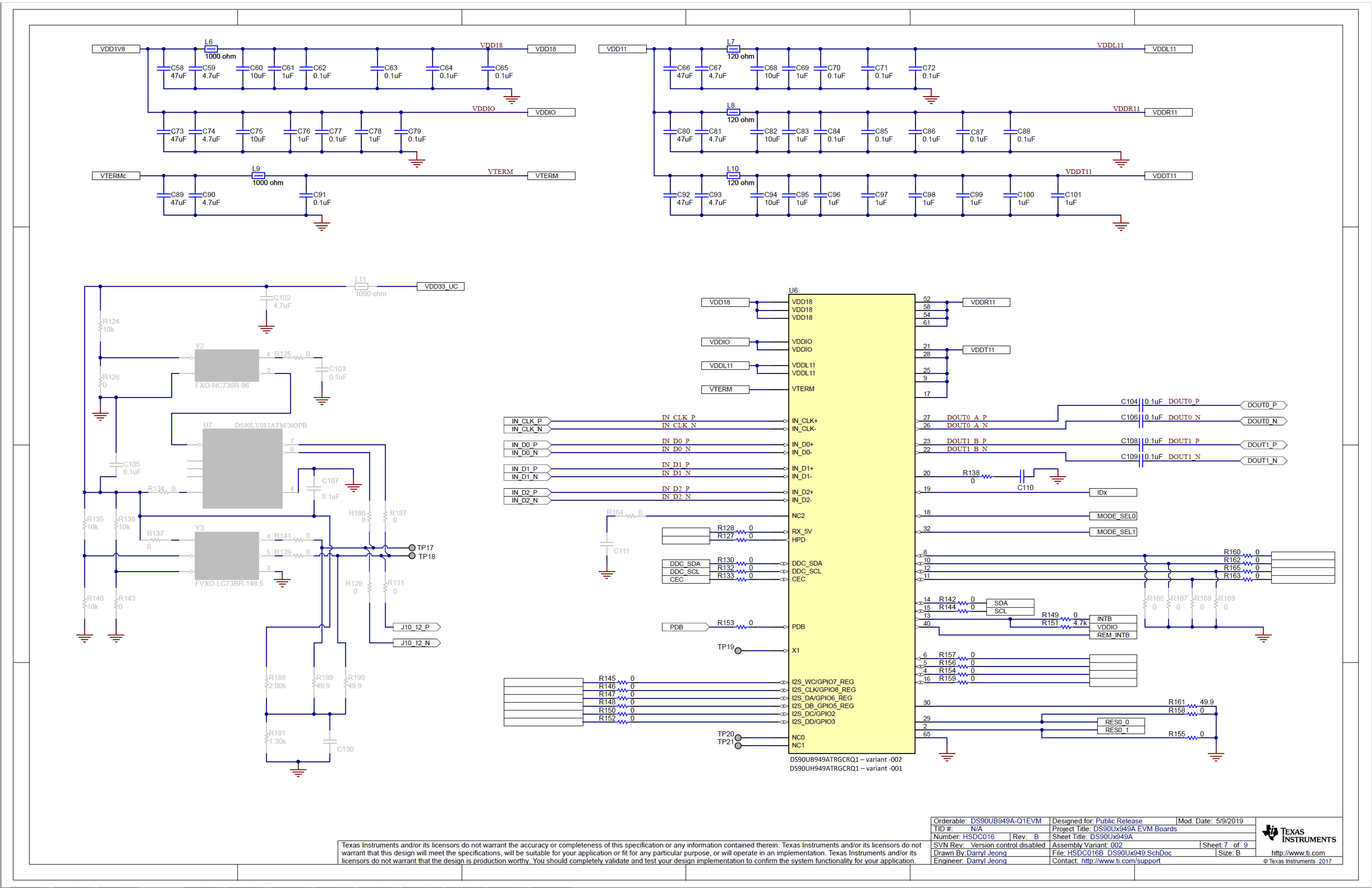 Figure A-2 Schematic - DS90UH949A-Q1 and Power Decoupling
 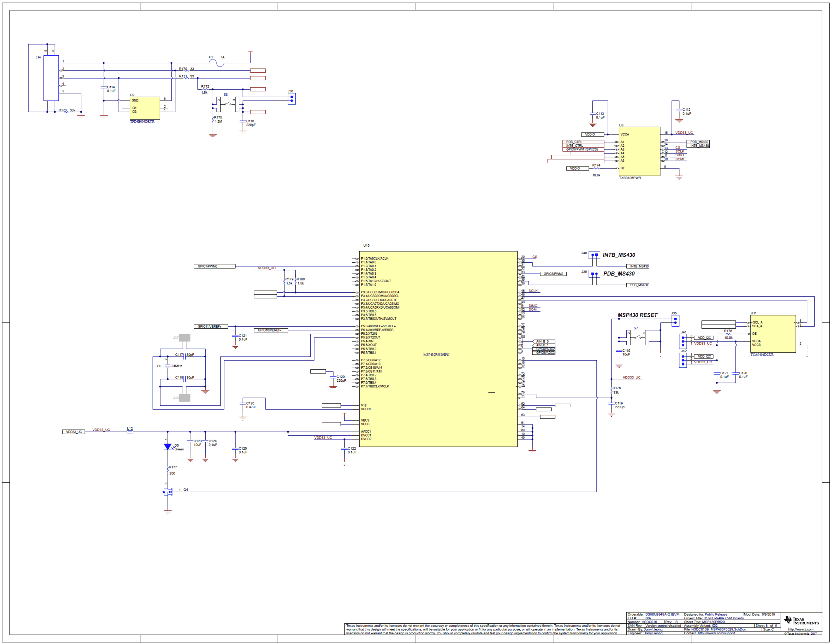 Figure A-3 Schematic - MSP430
 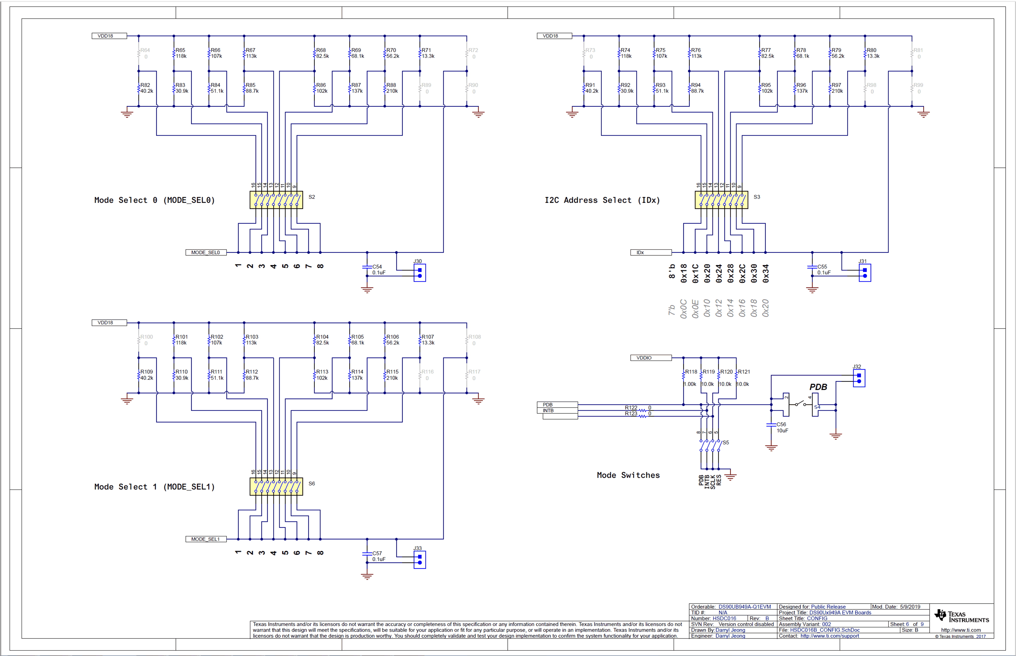 Figure A-4 Schematic - PDB, IDx and MODE_SEL Switches
 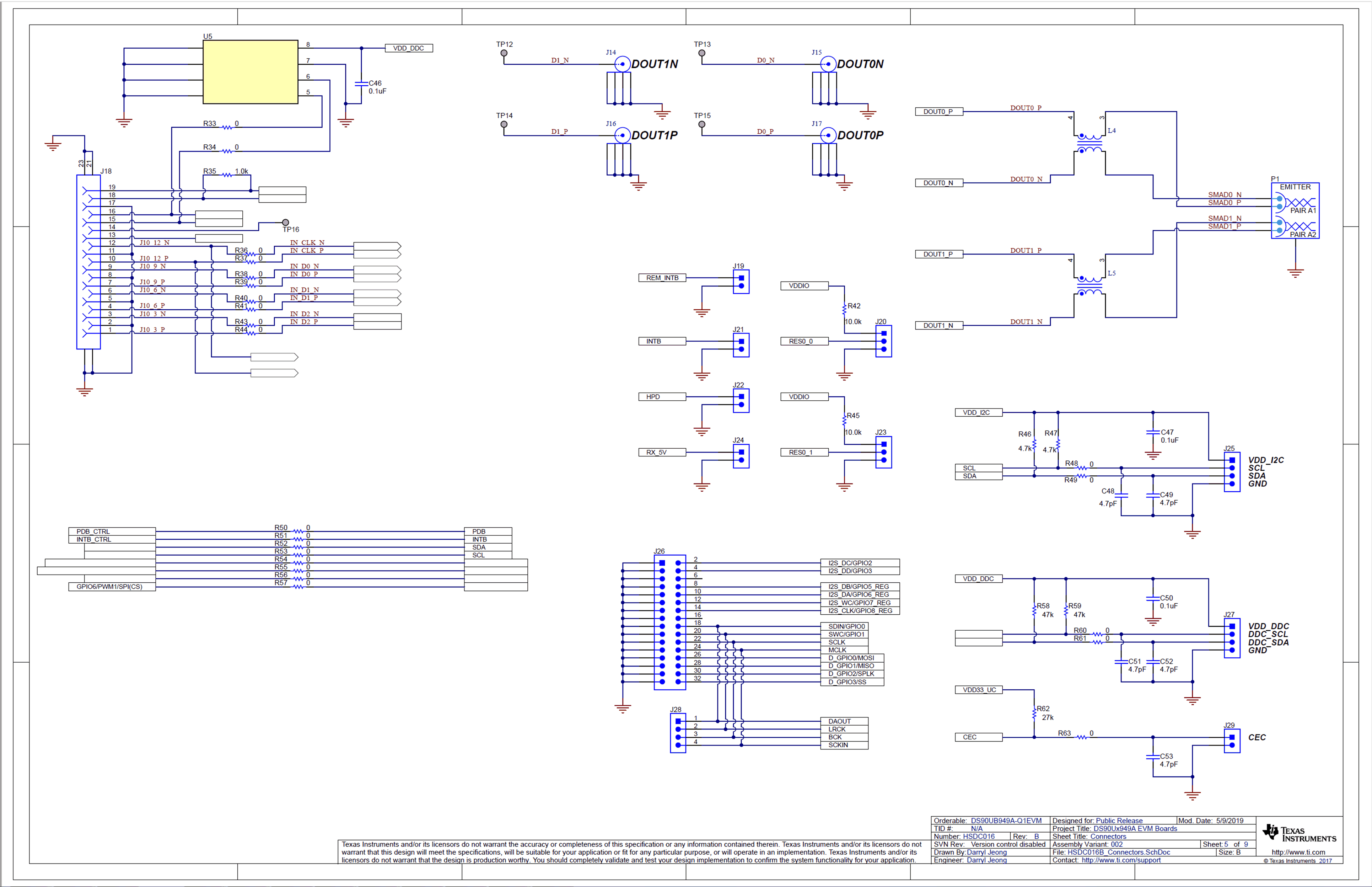 Figure A-5 Schematic - HDMI, HSD, SMA, I2C, DDC, CEC and GPIO/I2S/SPI Connectors
 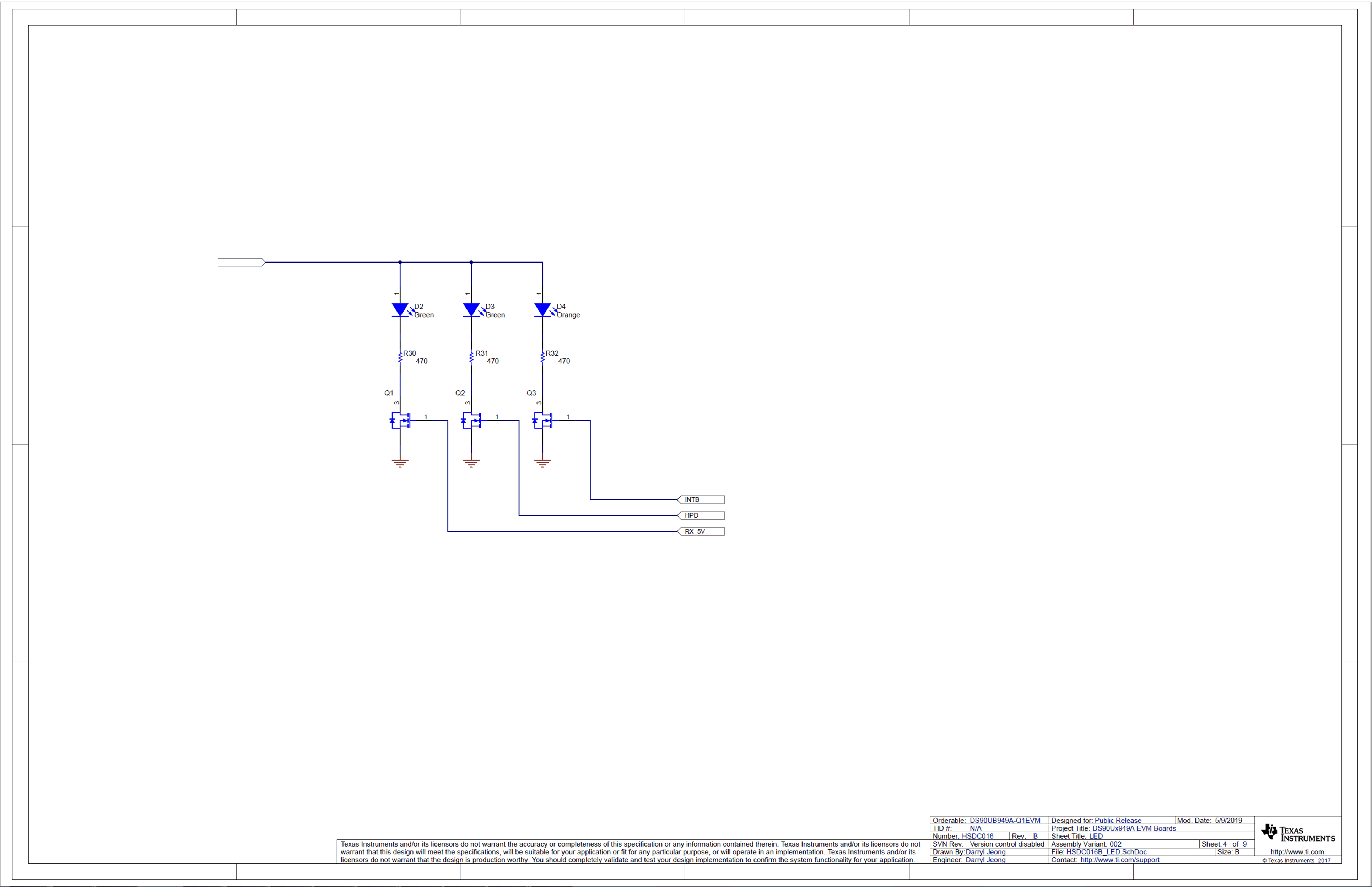 Figure A-6 Schematic - LEDs
 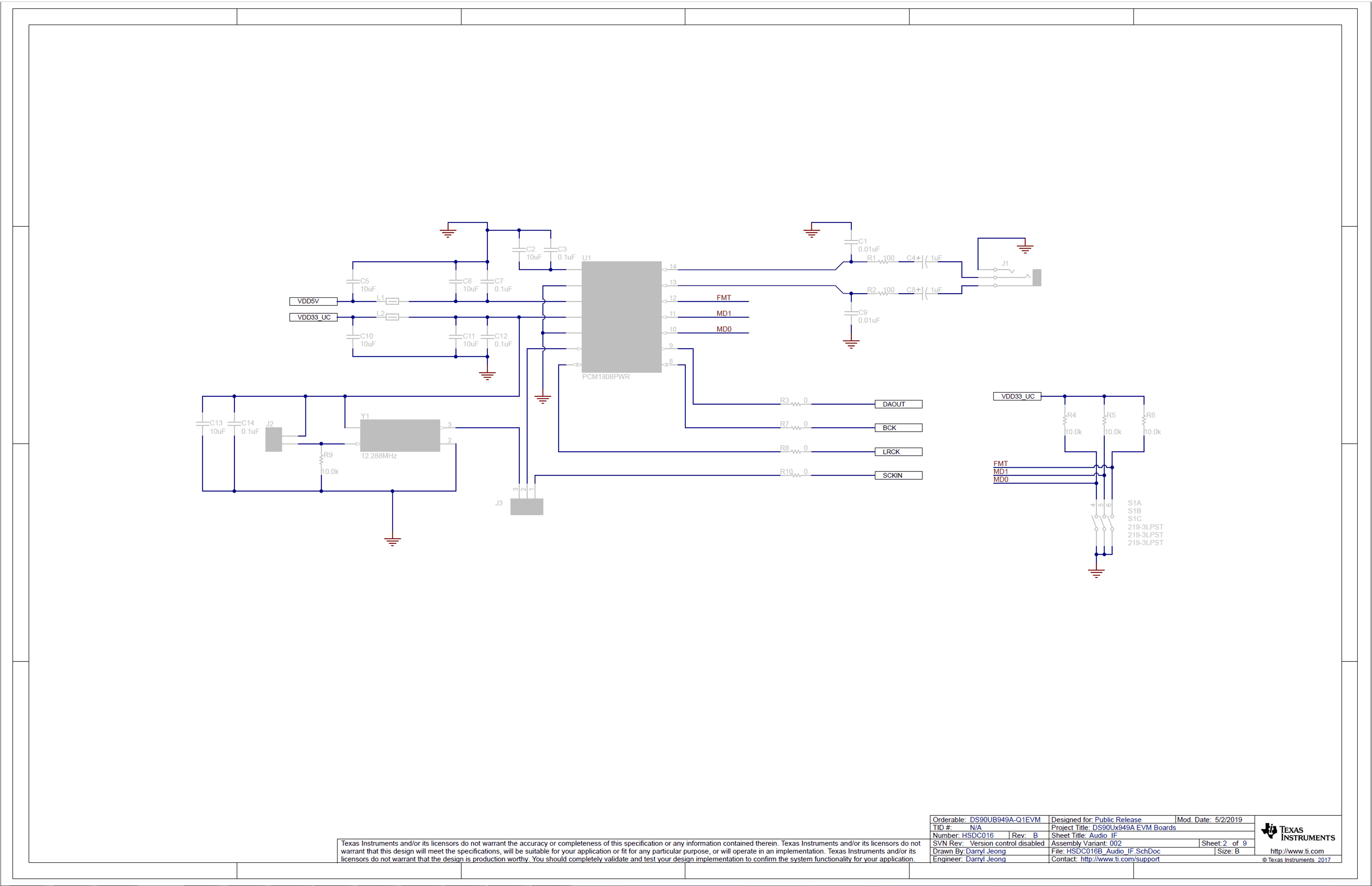 Figure A-7 Schematic - Audio (Not Populated)
 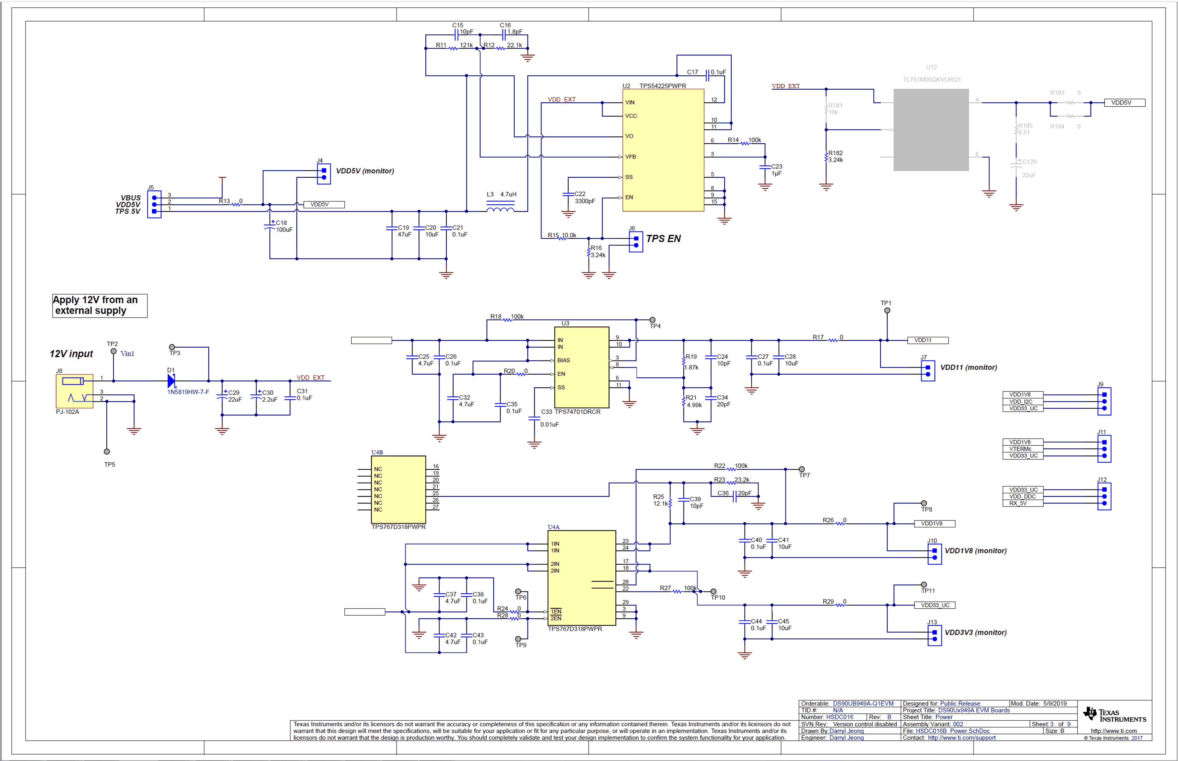 Figure A-8 Schematic - Power Regulators
 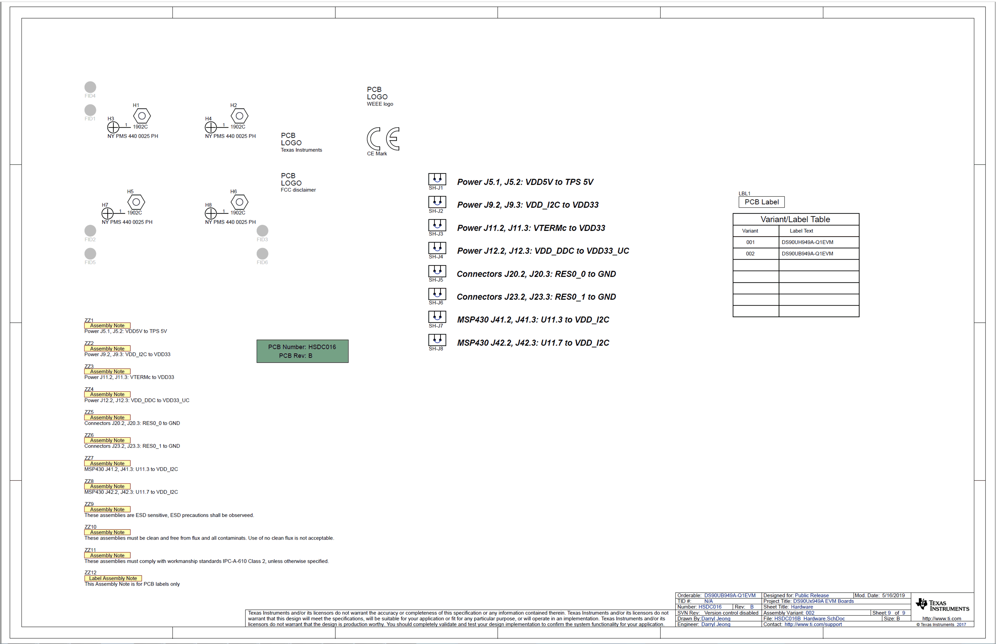 Figure A-9 Schematic - Hardware