ZHCSHC3B january   2018  – june 2023 TPS61280D , TPS61280E , TPS61281D

PRODUCTION DATA  

  1.   1
  2. 特性
  3. 应用
  4. 说明
  5. Revision History
  6. 说明(续)
  7. Device Comparison Table
  8. Pin Configuration and Functions
  9. Specifications
    1. 8.1 Absolute Maximum Ratings
    2. 8.2 ESD Ratings
    3. 8.3 Recommended Operating Conditions
    4. 8.4 Thermal Information
    5. 8.5 Electrical Characteristics
    6. 8.6 I2C Interface Timing Characteristics #GUID-BD85FD7C-B9AF-4F5D-9DFF-CD61365A592A/SLVS5401494
    7. 8.7 I2C Timing Diagrams
    8. 8.8 Typical Characteristics
  10. Detailed Description
    1. 9.1 Overview
    2. 9.2 Functional Block Diagram
    3. 9.3 Feature Description
      1. 9.3.1 Voltage Scaling Management (VSEL)
      2. 9.3.2 Spread Spectrum, PWM Frequency Dithering
    4. 9.4 Device Functional Modes
      1. 9.4.1 Power-Save Mode
      2. 9.4.2 Pass-Through Mode
      3. 9.4.3 Mode Selection
      4. 9.4.4 Current Limit Operation
      5. 9.4.5 Start-Up and Shutdown Mode
      6. 9.4.6 Undervoltage Lockout
      7. 9.4.7 Thermal Shutdown
      8. 9.4.8 Fault State and Power-Good
    5. 9.5 Programming
      1. 9.5.1 Serial Interface Description (TPS61280D/E)
      2. 9.5.2 Standard-, Fast-, Fast-Mode Plus Protocol
      3. 9.5.3 HS-Mode Protocol
      4. 9.5.4 TPS6128xD/E I2C Update Sequence
    6. 9.6 Register Maps
      1. 9.6.1  Slave Address Byte
      2. 9.6.2  Register Address Byte
      3. 9.6.3  I2C Registers, E2PROM, Write Protect
      4. 9.6.4  E2PROM Configuration Parameters
      5. 9.6.5  CONFIG Register [reset = 0x01]
      6. 9.6.6  VOUTFLOORSET Register [reset = 0x02]
      7. 9.6.7  VOUTROOFSET Register [reset = 0x03]
      8. 9.6.8  ILIMSET Register [reset = 0x04]
      9. 9.6.9  Status Register [reset = 0x05]
      10. 9.6.10 E2PROMCTRL Register [reset = 0xFF]
  11. 10Application and Implementation
    1. 10.1 Application Information
    2. 10.2 Typical Application
      1. 10.2.1 TPS61281D with 2.5V-4.35 VIN, 1500 mA Output Current (TPS61280D with default I2C Configuration)
        1. 10.2.1.1 Design Requirement
        2. 10.2.1.2 Detailed Design Parameters
          1. 10.2.1.2.1 Inductor Selection
          2. 10.2.1.2.2 Output Capacitor
          3. 10.2.1.2.3 Input Capacitor
          4. 10.2.1.2.4 Checking Loop Stability
        3. 10.2.1.3 Application Performance Curves
      2. 10.2.2 TPS61282D with 2.5V-4.35 VIN, 2000 mA Output Current (TPS61280D with I2C Programmable)
        1. 10.2.2.1 Design Requirements
        2. 10.2.2.2 Detailed Design Procedures
        3. 10.2.2.3 Application Performance Curves
  12. 11Power Supply Recommendations
  13. 12Layout
    1. 12.1 Layout Guidelines
    2. 12.2 Layout Example
    3. 12.3 Thermal Information
  14. 13Device and Documentation Support
    1. 13.1 Device Support
      1. 13.1.1 第三方产品免责声明
    2. 13.2 接收文档更新通知
    3. 13.3 支持资源
    4. 13.4 Trademarks
    5. 13.5 静电放电警告
    6. 13.6 术语表
  15. 14Mechanical, Packaging, and Orderable Information
    1. 14.1 Package Summary

封装选项

机械数据 (封装 | 引脚)
散热焊盘机械数据 (封装 | 引脚)
订购信息

说明

TPS6128xD/E 器件可以为由锂离子、富镍、硅阳极或磷酸铁锂电池供电的产品提供电源解决方案。电压范围针对诸如智能手机或平板电脑内单节电池便携式应用进行了优化。

TPS6128xD/E 可用作高功率预稳压器,延长电池运行时间并克服受电系统的输入电流和电压限制。

在关断情况下,TPS6128xD/E 运行在真正的直通模式下,静态耗电仅为 3µA,可充分延长电池寿命。

运行期间,当电池处于良好的充电状态中时,一个低欧姆、高效集成直通路径将电池连接至受电系统。

如果电池进入较低的充电状态,并且其电压变为低于所需的最小系统电压时,此器件无缝转换至升压模式以利用整个电池容量。

器件信息(1)
器件型号封装封装尺寸(标称值)
TPS61280DDSBGA (16)1.66mm x 1.66mm
TPS61281D
TPS61282D
TPS61280E
要了解所有可用封装,请参见数据表末尾的可订购产品附录。
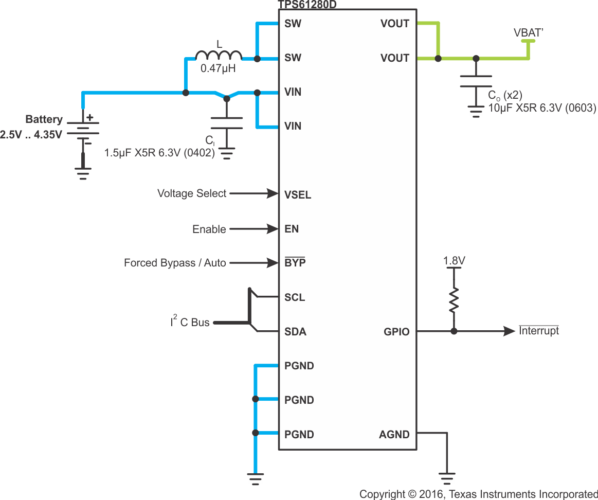
GUID-BCCF4A88-434E-45F7-8B00-E61B1ABAE5D9-low.gif简化版原理图