ZHCU837 December 2021
- 说明
- 资源
- 特性
- 应用
- 5
- 1System Description
-
2System Overview
- 2.1 Block Diagram
- 2.2 Highlighted Products
- 2.3
Design Considerations
- 2.3.1
Design Hardware Implementation
- 2.3.1.1 Hall-Effect Switches
- 2.3.1.2 Linear Hall-Effect Sensor Output
- 2.3.1.3 Power Supply
- 2.3.1.4 Transistor Circuit for Creating High-Voltage Enable Signal
- 2.3.2 Alternative Implementations
- 2.3.1
Design Hardware Implementation
- 3Hardware, Software, Testing Requirements, and Test Results
- 4Design and Documentation Support
2.2.1 DRV5056
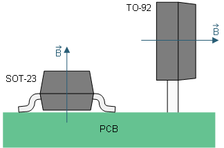
The DRV5056 is a linear Hall-effect sensor that responds proportionally to positive magnetic flux density readings. The device uses a ratiometric architecture that can reduce error from VCC tolerance when the external analog-to-digital converter (ADC) uses the same VCC for its reference. The DRV5056 is sensitive to the magnetic field component that is perpendicular to the die inside the package. Figure 2-3 shows the direction of sensitivity for the DRV5056.
 Figure 2-3 DRV5056 Direction of Sensitivity
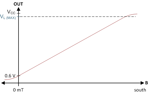
This design uses the TO-92 through-hole package. For the TO-92 package of this device, a positive magnetic flux density is defined as when the magnetic south pole applied near the front (marked) of the package or a north pole applied from behind the package. Figure 2-4 shows the magnetic response of the device. This device is a unipolar device, where the analog output drives 0.6 V when no magnetic field is present and increases as the positive field becomes stronger.
 Figure 2-4 DRV5056 Magnetic Response
The bipolar DRV5055 can be used an alternative to the DRV5056. The DRV5055 responds to both positive and negative fields instead of just negative fields. The advantage of the DRV5055 is that it can still work if the magnet was accidentally installed backwards since the device senses both negative and positive fields (note that the wake-up and stray field sensors will not work if the magnets are reversed because they are unipolar as well). For the head-on configuration used in this design, the linear Hall sensor is only exposed to either a positive field or a negative field during the trigger movement; it is not exposed to both fields when the trigger is pressed. For more information, see the Head-on Linear Displacement Sensing Using Hall-Effect Sensors application brief. As a result, only half the range of the DRV5055 is used if the DRV5055 is used as the linear Hall sensor for the design. Since the DRV5056 is a unipolar device; however, the entire range of the DRV5056 can be used. To maximize output dynamic range, the DRV5056 was selected in this design instead of the DRV5055.
The DRV5056A1 device variant was selected in this design because its magnetic range (20 mT) is near the maximum magnetic flux density that is expected to be detected by the DRV5056 based on the magnet material, magnet dimensions, and the distance from the magnet to the DRV5056 sensing element.