SWRA671 June 2020 CC1312R , CC1312R , CC1314R10 , CC1314R10 , CC1352P , CC1352P , CC1352R , CC1352R , CC1354P10 , CC1354P10 , CC1354R10 , CC1354R10 , CC2652P , CC2652P , CC2652R , CC2652R , CC2652R7 , CC2652R7 , CC2652RB , CC2652RB , CC2652RSIP , CC2652RSIP
-
Cloning Z-Stack Network Properties Using the SimpleLink Wireless MCU Family
- Trademarks
- 1 Introduction
- 2 Abbreviations and Acronyms
- 3 Tool Versions
- 4 Trust Center and Non-Volatile Memory
- 5 Multi-Page NVM
- 6 MT Interface
- 7 Zigbee Coordinator Setup Procedure
- 8 Zigbee Coordinator Cloning Procedure
- 9 Zigbee Coordinator Cloning Procedure Example
- 10 Other Application Considerations
- 11 Summary
- 12 References
- A TI Zigbee Network Properties Cloning Tool Guide
- B Establishing a Serial Connection
9 Zigbee Coordinator Cloning Procedure Example
This section provides a detailed example of the procedure outlined in Section 8. A sniffer log was used to ensure proper functionality. Before executing this example, a network was formed with a Zigbee Coordinator (ZC1), a CC135xR1 Launchpad running a modified version of the ZC light example project following the setup from Section 7. After the network was created, two ZRs joined the network.
- Identify the COM Ports for the devices: ZC1- COM20, ZC2- COM23
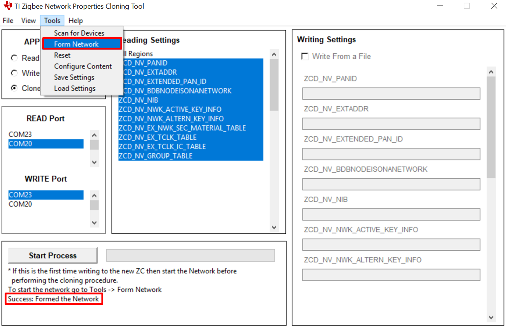
- Open the TI Zigbee Network Properties Cloning tool, and select the 'Clone' option then the designated ports from step 1. Afterwards, go to Tools -> Form Network. A network will be formed on ZC2 when the 'Clone' option is selected. If a network is formed the output should show a success, if not a failure message will be displayed.
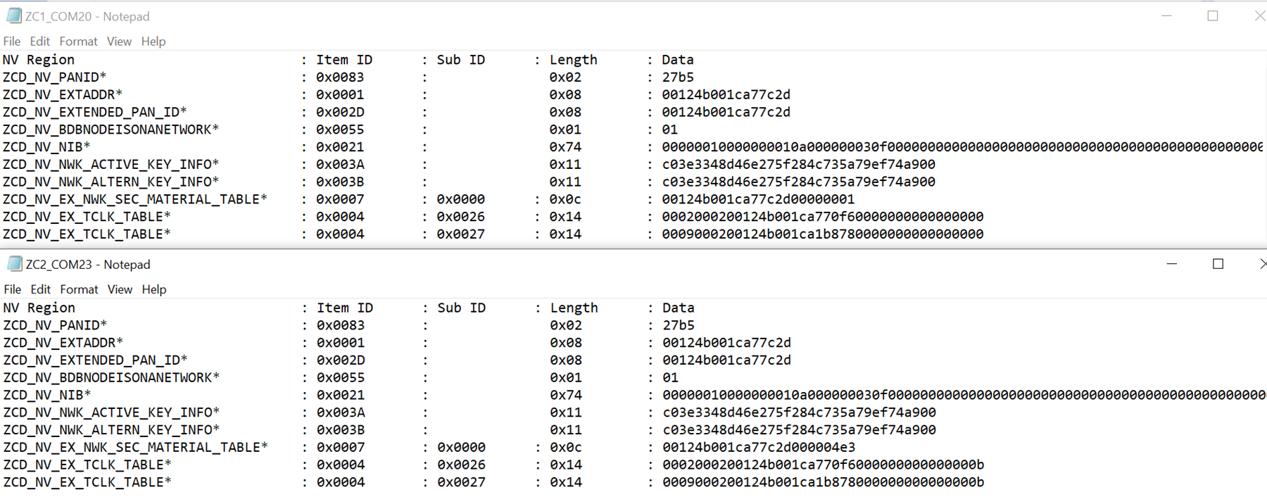
- Press the 'Start' button and observe the output display to verify what was read and written. If desired the content from both ZC1 and ZC2 can be compared by analyzing the differences between their read_content.txt file output after reading from each device separately. If the content from both files is the same then the procedure was successful.
- Remove ZC1 from the NWK.
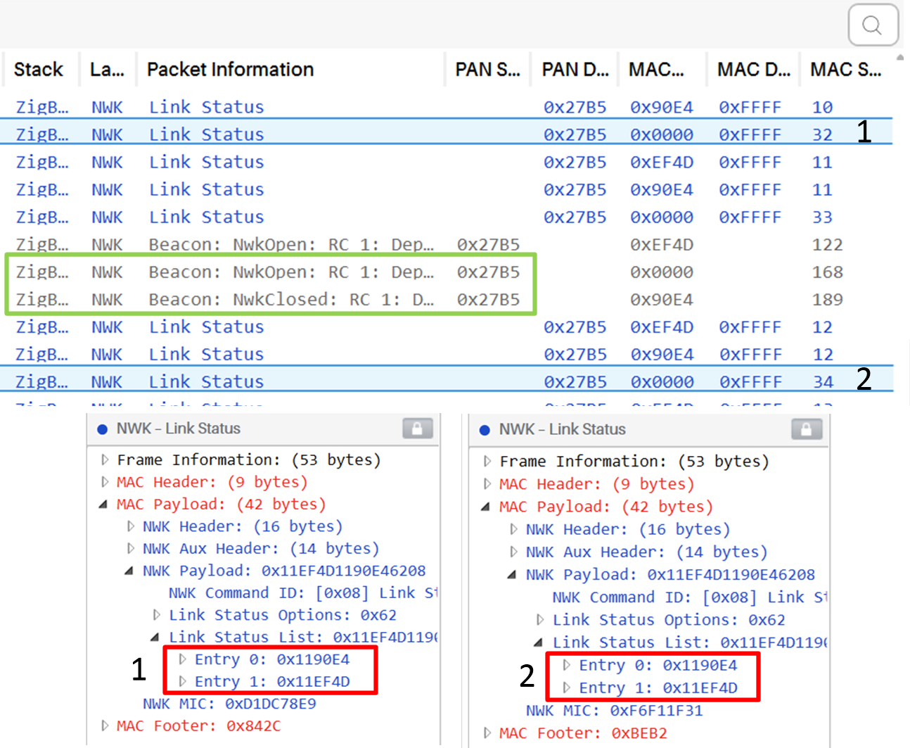
- Power Cycle or Restart ZC2. After ZC2 is part of the already existing network it will send out periodic link statuses. Within the status should be the devices that had joined when ZC1 was the coordinator.
- The network should continue to operate as before.
Figure 1. Formed Network Example

Figure 2. NV Content Read Example

This image shows an example of what was read from ZC1 (Top) and from ZC2 (Bottom). The contents of TCLK were shorted to only show the last two table entries. This is so because the TCLK table gets populated from the end of the table first.
Figure 3. Sniffer Log Capture Example

This image is part of the sniffer log that was captured for this example. In link status (1), sent by the coordinator device ZC1 (0x0000), we can confirm that there were two devices who were part of the network. The green box shows ZC2 joining the network as ZC1 leaves signified by the opening and closing of the network. Link status (2), sent by the new coordinator ZC2, still shows the same devices as part of its network.