SPRACO3 October 2019 INA240 , LMG5200 , TMS320F280021 , TMS320F280021-Q1 , TMS320F280023 , TMS320F280023-Q1 , TMS320F280023C , TMS320F280025 , TMS320F280025-Q1 , TMS320F280025C , TMS320F280025C-Q1 , TMS320F280040-Q1 , TMS320F280040C-Q1 , TMS320F280041 , TMS320F280041-Q1 , TMS320F280041C , TMS320F280041C-Q1 , TMS320F280045 , TMS320F280048-Q1 , TMS320F280048C-Q1 , TMS320F280049 , TMS320F280049-Q1 , TMS320F280049C , TMS320F280049C-Q1 , TMS320F28374D , TMS320F28374S , TMS320F28375D , TMS320F28375S , TMS320F28375S-Q1 , TMS320F28376D , TMS320F28376S , TMS320F28377D , TMS320F28377D-EP , TMS320F28377D-Q1 , TMS320F28377S , TMS320F28377S-Q1 , TMS320F28378D , TMS320F28378S , TMS320F28379D , TMS320F28379D-Q1 , TMS320F28379S
-
Dual-Axis Motor Control Using FCL and SFRA On a Single C2000 MCU
- Trademarks
- 1 Introduction
- 2 Benefits of the C2000 for High-Bandwidth Current Loop
- 3 Current Loops in Servo Drives
- 4 PWM Update Latency for Dual Motor
- 5 Outline of the Fast Current Loop Library
- 6 Evaluation Platform Setup
- 7 System Software Integration and Testing
- 8 Summary
- 9 References
4 PWM Update Latency for Dual Motor
The major challenge in implementing the current loop lies in reducing the latency between feedback sampling and PWM updates. In traditional control schemes, this latency is typically one sampling period, thereby, delaying the control action. In other words, it leads to one sampling period of inaction to any disturbances in the loop. For a fast current loop, this delay must be as small as possible to improve the loop performance over the wide operating speed range of the motor. Typically, a latency of one microsecond or less is considered acceptable in many applications that requires a controller with a fast compute engine, a fast ADC, low latency control peripherals and a superior control algorithm.
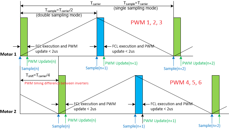
On a single F2837x or F28004x, it is possible to run two independent FCLs in less than 2 µs while still supporting the high control bandwidth and double sampling of each axis. In order to maintain the goal of measuring the currents of each motor during voltage transitions, the ADC double sampling is interleaved between each motor so that the sampling and subsequent FOC processing does not need to happen back to back. The motor 1 carrier lags motor 2 by a fixed 90°, then the ADC sampling period is consistent across both motors but interleaved between them as shown in Figure 2. Each ADC sample and conversion is followed by the C2000 CPU performing the FOC algorithm and updating the PWMs. In this way, the sample-to-PWM update remains very consistent for each execution, whether it’s the first or second sample of motor 1 or motor 2.
 Figure 2. Motor Phase Current Sampling and PWM Update for Dual Motor