SLWU079D March 2012 – April 2016
-
TSW140x High Speed Data Capture/Pattern Generator Card
- Trademarks
- 1 Functionality
- 2 Hardware Configuration
- 3 Software Start up
- 4 ADC Data Capture Software Operation
- 5 TSW1400 Pattern Generator Operation
- 6 TSW1405 Functional Description
- 7 TSW1406 Functional Description
- 8 Revision History
3.2 USB Interface and Drivers
The HSDC Pro GUI will first attempt to connect to the EVM USB interface. If the GUI identifies a valid board serial number, a pop-up will open displaying this value, as shown in Figure 2. The serial number also has an EVM type number attached to it. This indicates to the GUI which TSW140x board is presently connected to the host PC. It is possible to connect several TSW140x EVMs to one host PC but the GUI can only connect to one at a time. If multiple boards are connected to the PC, the pop-up displays all of the serial numbers found. It is then up to the user to select which board the GUI will be associated with.
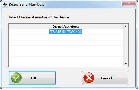 Figure 2. TSW140x EVM Serial Number
 Click on “OK” to connect the GUI to the board. If the FPGA firmware version read by the GUI does not match the firmware to be used as determined by the device selected (see section 4.1 for more info on device selection), the following message appears as shown in Figure 3. This message also appears after power up as the FPGA is not programmed.
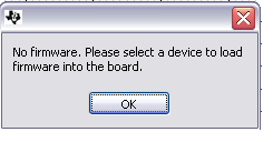 Figure 3. Firmware Does Not Match the Device Selected
 Click on “OK”. The Top level GUI now opens and appears as shown in Figure 4.
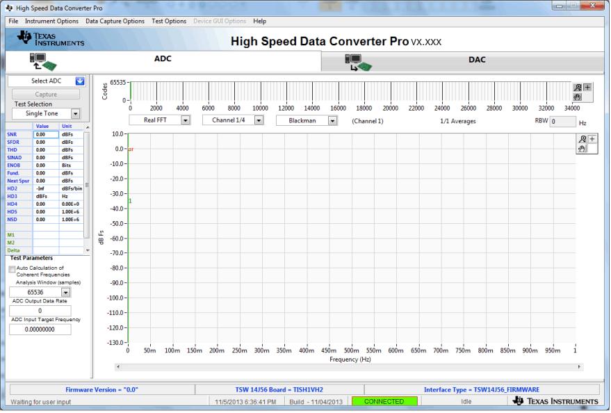 Figure 4. TSW140x EVM GUI Top Level
 After the software has established a connection, if the message “Board not Connected” opens, double check the USB cable connections and that power is present. If the cable connections appear fine, try establishing a connection by clicking on the “Instrument Option” tab at the top left of the GUI and select “Connect to the Board” (see Figure 5). If this still does not correct this issue, check the status of the host USB port.
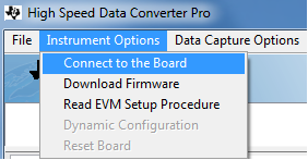 Figure 5. Connecting GUI to the EVM
 When the software has been installed and the USB cable has been connected to the TSW140x EVM and the PC, the TSW140x USB serial converter should be located in the Hardware Device Manager under the Universal Serial Bus controllers as shown in Figure 6. This is a quad device which is why there is an A, B, C, and D USB Serial Converter shown. When the USB cable is removed, these four will no longer be visible in the Device Manager. If the drivers are present in the Device Manager window and the software still does not connect, cycle power to the board and repeat the steps above.
If the GUI starts up but freezes before it brings up the "Connected to Board" dialog, or takes an unusually long time for other actions to occur, it is possible the USB being used from the host PC is operating at USB 1.0 speeds. A common indication of this is when the status bar on the bottom left of the screen keeps reading "Disable all Controls" upon loading the software without ever going to the "Connect Board Dialog". The GUI is designed to run at USB 2.0 speeds and some computers have USB 1.0 ports on the front panel and 2.0 on the back panel. Using the ports on the back of the PC if at all possible is recommended.
The .exe file installs the FTDI drivers during software installation. If after connecting the USB cable and Windows lists the board as an "unknown device", this could be caused by corrupted FTDI drivers being installed on the computer. This happens in cases where the same computer has been used to interface with previous products that used FTDI drivers. In this case, users are advised to download and install a utility from FTDI at http://www.ftdichip.com/Support/Utilities/CDMUninstaller_v1.4.zip.
The help file for using this utility is found at:
http:/www.ftdichip.com/Support/Utilities/CDM_Uninst_GUI_Readme.html
Users will need to use the following hex values to uninstall previous versions of the ftdi drivers:
Vendor ID (VID): 0403
Product ID (PID): 6010
After removing the drivers for this PID and VID, re-connect the TSW140x USB cable and check if the TSW140x ports get listed properly in Device Manager.
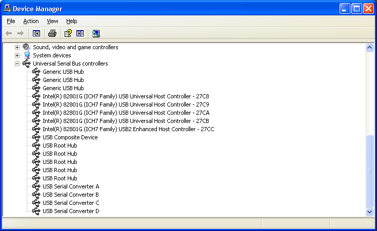 Figure 6. Hardware Device Manager