TIDUEW7 May 2020
- Description
- Resources
- Features
- Applications
- Design Images
- 1System Description
-
2System Overview
- 2.1 Block Diagram
- 2.2 Design Considerations
- 2.3 Highlighted Products
- 2.4 System Design Theory
- 3Getting Started, Testing Setup, and Test Results
- 4Design Files
- 5Software Files
- 6Related Documentation
2.2.5 LCD Screen Connector
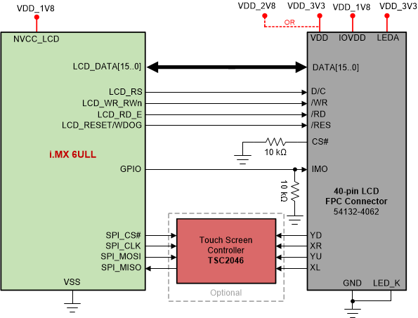
This design has a mountable LCD screen. The i.MX 6ULL processor's LCD interface can be used to control a wide range of display devices varying in size and capability. Many of these displays have an asynchronous parallel MPU interface for command and data transfer to an integrated frame buffer. There are other popular displays that support moving pictures and require the RGB interface mode (called DOTCLK interface in this document) or the VSYNC mode for high-speed data transfers. In addition to these displays, it is also common to provide support for digital video encoders that accept ITU-R BT.656 format. The goal is to select an LCD screen that is suitable for the application and compatible with the processor.
The Newhaven Display NHD-2.4-240320CF-CTXI#-F backlight and LCD screen selected for this design can make use of the already available 3.3 V and 1.8 V supply voltages so we can eliminate the need for additional voltage regulators. Additionally, this display is compatible with the processor and exceeds the simple requirements of a data concentrator application. The LCD interface is connected through 40-pin FPC connector. The connection diagram of the LCD interface is shown in Figure 8.
| DESCRIPTION | MFG. | PART NUMBER |
|---|---|---|
| Display, TFT LCD, 240x320, 8/16-bit Parallel MPU Interface | Newhaven Display | NHD-2.4-240320CF-CTXI#-F |
| Conn, FPC, Receptacle, 1x40, 0.5mm, 0.5A, Bottom Contact, RA, SMD | Hirose Electric Co Ltd | FH40-50S-0.5SV |
| IC, TSC2046, Touch Screen Controller, TSSOP-16 | Texas Instruments | TSC2046IPWR(1) |
