SNLU296A December 2022 – December 2022
5.3.3 Crosspoint Switch
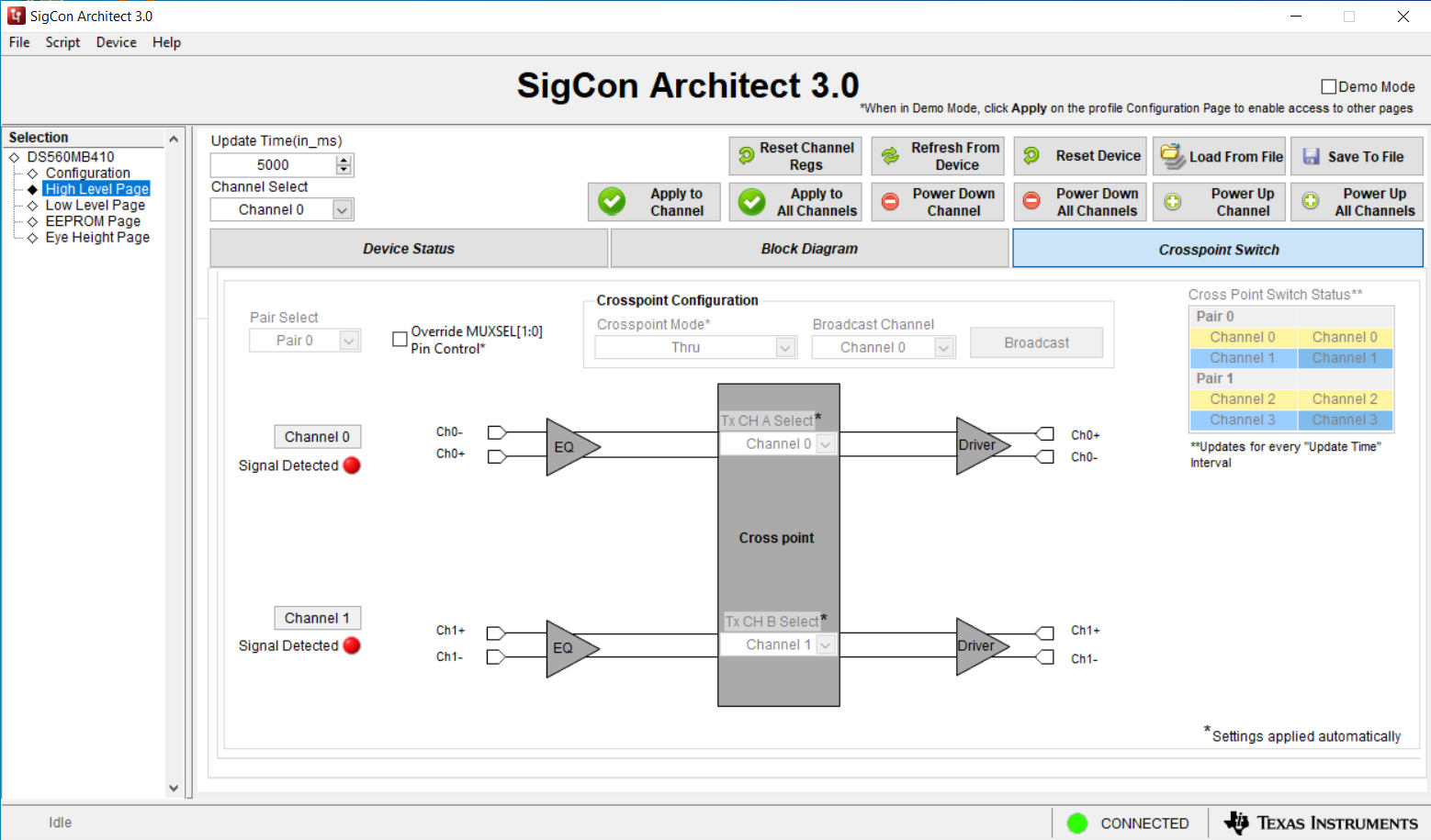
The Crosspoint Switch tab enables configuration of the device crosspoint. The crosspoint allows for channel pairs to be switched between Through, Lane Crossing, and Fanout modes. To make changes in the crosspoint page, Override MUXSEL[1:0] Pin Control must be selected. Once overridden, changes made to the crosspoint configuration are automatically applied to the device, without the use of the Apply to Channel button.
 Figure 5-9 Crosspoint Switch Tab
Table 5-3 Crosspoint Switch Settings and
Buttons
|
Seting or Button Name |
Behavior |
|---|---|
| Update Time | Sets the time interval at which the device status is updated. |
| Channel Select | This setting is
persistent when switching between the Device Status, Block
Diagram, and Crosspoint Switch tabs. This setting is used to select which channel will be written to when Apply to Channel is clicked. |
| Refresh From Device | Reads register data from the device. This data will then be updated in the DS560MB410 Profile pages. |
| Reset Device | Resets all device registers to their default values. |
| Load From File | Opens a window allowing the user to select a file with register data. Once the appropriate file is selected, register data from the file will be written to device registers. |
| Save To File | Opens a window enabling the user to save device register data to their computer. This file contains data for all of the device registers. |
| Override MUXSEL[1:0] Pin Control | Enables register control of the device crosspoint. This must be selected to make changes to the crosspoint configuration. |
| Pair Select | Selects the pair of channels that the Crosspoint Mode is applied to. Pair 0 corresponds to channels 0-1. Pair 1 corresponds to channels 2-3. |
| Crosspoint Mode | Selects the crosspoint configuration for the selected channels. User can select between Through, Lane Crossing, and Fanout modes. When the Fanout mode is selected, it is necessary to select which channel is being broadcasted. |
| Broadcast Channel | Selects which channel is broadcasted while a crosspoint is in Fanout mode. After a selection is made, it is necessary to click the Broadcast button for changes to apply. |