SLAU857A May 2021 – July 2021 MSP430FR2476 , MSP430FR2512 , MSP430FR2522 , MSP430FR2532 , MSP430FR2533 , MSP430FR2632 , MSP430FR2633 , MSP430FR2672 , MSP430FR2673 , MSP430FR2675 , MSP430FR2676
5.2.3 MCU Widget Configuration
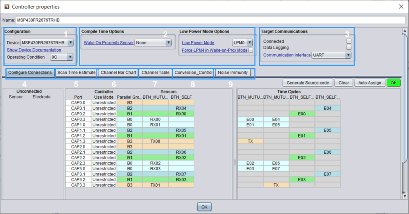
The MCU widget interface is shown in Figure 5-9. This part mainly configures the MCU model (No. 1); MCU working mode and low power consumption parameters (No. 2, 5, 8), anti-noise function (No. 9); mapping virtual pins to actual pins (No. 4). The parameters that need to be configured are shown in Table 5-3. The numbers in the boxes correspond to those in Figure 5-9. Other parameters are involved in Phase 2.
 Figure 5-9 MCU Widget Interface
| Number | Operation | Function | Recommended Value | Comment |
|---|---|---|---|---|
| 1 | Device | Select the device and package. | None | |
| Operating Condition | Choose the working temperature. | 25°C | Temperature affects the noise of the device and the Threshold Percentage in the sensor widget. | |
| 2 | Wake on Proximity Sensor | If there is a need for ultra-low power consumption, choose a Sensor that is used as a proximity wake-up sensor. | Can be unenabled | |
| Low-Power Mode | Choose the low-power mode according to system requirements. | Can use default configuration | LPM3 has lower power consumption than LPM0, but it cannot actively receive UART data and can only send data. | |
| Force LPM4 in Wake-on-Prox Mode | When enabled, the MCU consumes less power in Wake-on-Prox mode. | Can be unenabled | After enabling, the timing clock source is VLO clock, the timing error is relatively large. | |
| 3 | Communication Interface | Choose UART or BUCK_I2C to communicate with the GUI. | None | See Section 4.2.1 for the communication pins and IRQ PIN used. |
| 4 | Configure Connections | According to the actual button design, map the virtual Tx and Rx pins to the CAP I/O pins. | Can click “Auto-Assign” | In addition to the button and proximity sensor function, it is recommended to select the Auto-Assign function. |
| 5 | Scan Time Estimate | Automatically calculate the total scanning time of the button in Active mode. | None | Used to evaluate the shortest "Active Mode Scan Rate ms". |
| 8 | Active Mode Scan Rate ms | Set the scan time interval of the sensor in active mode according to requirements. | Can use default configuration | |
| Wake on Prox Mode Scan Rate ms | Set the scan time interval of the proximity sensor in Wake-on-Prox mode. | Can use default configuration | The shorter the time, the faster the scanning speed close to wake-up, but the higher the power consumption. | |
| 9 | Enable Noise Immunity | Enable noise immunity function. | Can be unenabled | It is used to improve the anti-noise ability, but the amount of code is larger and the scanning time increases. |
| Self/Mutual mode Oversampling | Adjust oversampling level. | Can be unadjusted | Can improve the level of noise immunity, but oversampling increases the scan time of a single cycle. | |
| Dynamic Threshold Adjustment | Enable dynamic adjustment of proximity sensing and touch threshold. | Enable | After enabling, the sensitivity changes with the noise level, but when encountering sudden noise, the threshold change may lag behind the noise change. |
The "Configure Tx/Rx Groups" in the sensor widget store the Tx and Rx corresponding to the virtual button, and the "Configure Connections" in the MCU widget store the CAP X.X corresponding to the physical button. Correspond the physical buttons with the virtual buttons.
After configuration, as shown in Figure 5-10, when the OK button in the "Configure Connections" directory turns green, and the virtual pins are mapped correctly to the actual pins, you can click "Generate Source Code" to generate the code. Remember creating a new project will delete all files in the current folder!
 Figure 5-10 OK Button