SLAU857A May 2021 – July 2021 MSP430FR2476 , MSP430FR2512 , MSP430FR2522 , MSP430FR2532 , MSP430FR2533 , MSP430FR2632 , MSP430FR2633 , MSP430FR2672 , MSP430FR2673 , MSP430FR2675 , MSP430FR2676
2.1 Self-Capacitive Detection
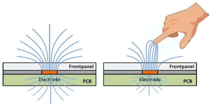
Taking the simplest single button as an example, Figure 2-2 shows a self-inductive capacitor, and Figure 2-3 shows the detection model. The self-inductive capacitor uses a single electrode (receiving electrode Rx) formed by copper coating to detect the change in capacitance of the electrode to the power line ground. The initial capacitance of the button to power line ground is Cp. When a human hand touches it, Ct, Ch, and Cg are introduced into the circuit, thereby increasing the capacitance of the button to ground.
 Figure 2-2 Self-Capacitive Detection
In Figure 2-3, the solid line indicates the PCB routing, and the dashed line indicates the touch-related routing. Gray components indicate equivalent capacitance or resistance.
Rh = Human body resistance.
Rs = Series resistance. The recommend value is 470 Ω.
Cp = The parasitic capacitance of the button and the connected wire to the power line ground.
Cg = The capacitance between the power line ground and the earth ground. For battery applications, it is approximately 1pF. For grounding applications, it is a short circuit.
Ch = Series capacitance between the human body and the earth ground.
Ct = The capacitance formed by the electrical level and the human fingertip, which is similar to the structure of a parallel plate capacitance.
For ease of analysis, the influence of Rh and Rs is ignored. Equation 1 shows the equivalent capacitance of the button to the power line ground. Sensitivity can be characterized as the ratio between the capacitance change caused by the touch and the base capacitance, as shown in Equation 1. Among them, Ch is larger than Cg and Ct, so it can be ignored.
The parallel plate capacitance is calculated by:
Where:
- A = The contact area between the finger and the sensor pad covering layer.
- d = The thickness of the overlay.
- ε0 = Air dielectric constant.
- εr = The dielectric constant of the overlay.
It can be seen from Equation 2 and Equation 3 that the methods to change the sensitivity are:
- Reduce the thickness of the cover plate to increase the sensitivity.
- Reduce the density of the grid ground, or increase the PCB thickness to reduce the sensitivity.
- Connect the power ground to the earth ground to increase the sensitivity.
- Increase the contact area A between the finger and the sensor pad covering layer to increase the sensitivity.
The electrode size cannot increase indefinitely. The main reason is that the maximum effective area of the parallel plate capacitance Ct is the same as the finger touch area. Therefore, Ct would also increase, resulting in a decrease in sensitivity.