ZHCA962 October 2019
- 说明
- 资源
- 特性
- 应用
- 设计图像
- 1System Description
- 2System Overview
- 3Hardware, Software, Testing Requirement and Test Result
- 4Design Files
- 5Software Files
- 6Related Documentation
3.2.1.3.2 PSE System Firmware GUI Operation
Start the PSE system firmware GUI by double clicking the GUI icon and clicking the Start button. A window similar to Figure 3 appears. The Offline mode is selected by default.
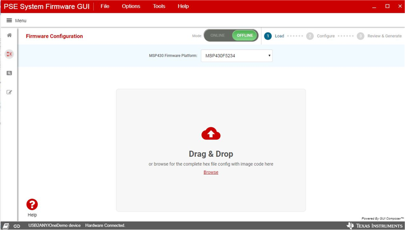
Select the MSP430 device you want to start with and then load the PSE system firmware code image (access from TIDA-050026-23882 folder or PSEMCUDAUEVM-082 tool folder). When finished, click Proceed to go to the configuration page.
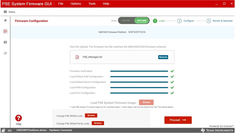
The configurations are split into four sections: system configuration, PPM (Port Power Management) configuration, device configuration, and port configuration.
The system configuration is applied to the whole system. This tab is always available on the to the right of the GUI. The following parameters can be configured through the system configuration tab:
- Legacy detection functions
- Use of external sensing circuit
- System bootup setting
- Turn on the PSE port as soon as the power is up.
- Turn on the PSE port after the PoE enable command is sent from the host
- Port overload retry mode
- Re-enable immediately: after overload happens, the port is re-enabled immediately. If the overload still presents, it will try at most five times and shuts down the port if the overload is not removed within five retries. The port is re-enabled after the PD is removed from the port and reconnects to the port.
- Re-enable after PD is disconnected and connected: after overload happens, the port is disabled immediately and is re-enabled after the PD is removed from the port and reconnects to the port.
- Timer controlled: the port is re-enabled immediately after overload happens. The port keeps retrying for a period (controller by timer) and is disabled after the timer expires. The port is re-enabled after the PD is removed from the port and reconnects to the port.
- OSS signal source (from MCU or CPLD):In a multi-power supply system, when one power supply has faults and the remaining power supply is not able to supply the current power consumption, turn off low priority ports to protect the remaining power supply. The OSS function of the PSE is used to fast shutdown the low priority ports. There are 2 sources to generate the OSS signal:
- MSP430 generates the OSS signal
- CPLD generates the OSS signal
- Interrupt mask
Legacy devices released prior to the PoE standard can be powered through the Ethernet cable. The PSE system firmware detects these legacy PDs and powers on with protection.
The external sensing circuit is used to measure the total power consumption of the system. When the current exceeds the power budget, the MCU shuts down low priority ports. This increases the system response to the load step change.
The interrupt mask in Figure 5 can be configured to enable interrupt events to notify the host through the MSP430 P6.0.
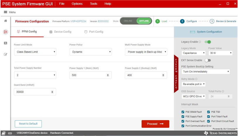
PPM configuration is applied to the port power management mechanism. The following parameters can be configured through the PPM configuration tab:
- Power limit mode:class limit mode and port limit mode
- Class limit mode:in class limit mode, the port power is limited by the PD's class level. For example, if the PD is class 8, the port power limit(PCUT) is set to 90W.
- Port limit mode:in port limit mode, the port power is limited by the host. The host should set port power limit before the port is powered on.
- Power policy: static and dynamic mode
- Static mode:in static mode, the port power allocation is set to port power limit. In class limit mode, port power allocation is class level power of the PD and in port limit mode, the port power allocation is the port power limit configured from the host.
- Dynamic mode: in dynamic mode, the port power allocation equals to the port's actual consumed power. It allocates the port's unused power to other ports.
- Multi-power supply mode: RPS and sharing mode:
- Redundant power supply (RPS) mode:in RPS mode, the total power budget equals to main power supply's power budget when both main power supply and backup power supply are connected. The total power budget equals to backup power supply's power budget when the main power supply is disconnected.
- Sharing power supply mode:in sharing mode, the total power budget equals to the sum of two power supplies' power budget when both power supplies are connected. The total power budget equals to remaining power supply's power budget if one of the power supplies is disconnected.
- Total number of power supplies and the power budget of each power supply. If there's only one power supply, the power good signal must be connected to P1.5.
- Power guard band: when the total allocated power < total power budget — guard band, there's no more low priority ports to be turned on and the guard band LED will turn on.
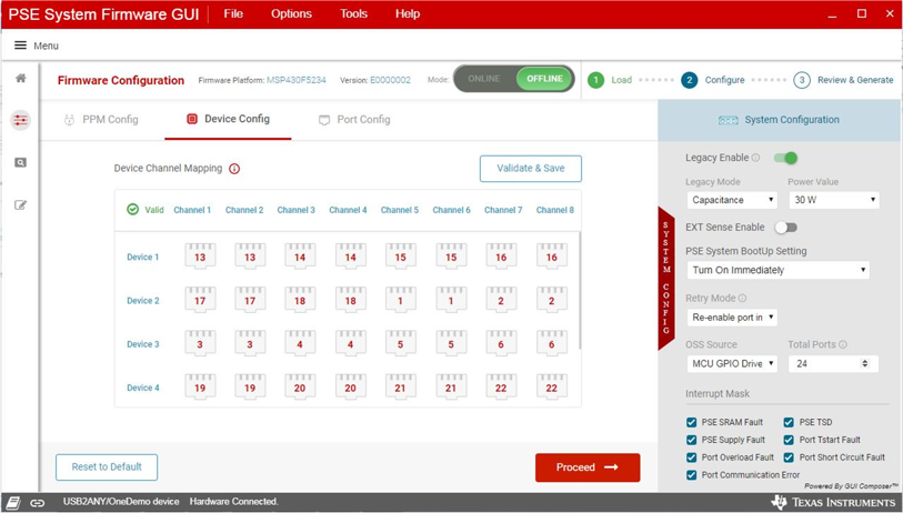
Device configuration is mainly used to configure the mapping between the PSE device channels and the logical RJ45 ports. When mapping a 4-pair port, only channels within the same quad (channel 1–4 or channel 5–8) can be mapped to one 4-pair port.
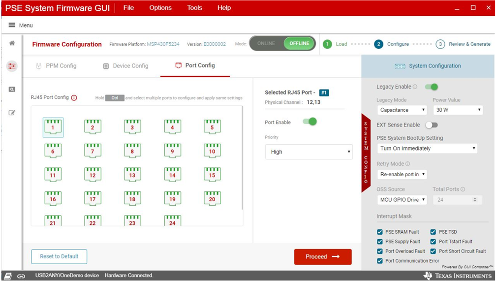
The Port Configuration is applied to the port by port settings, such as port PoE enable and disable, port priority, and port power limit (only in port limit mode).
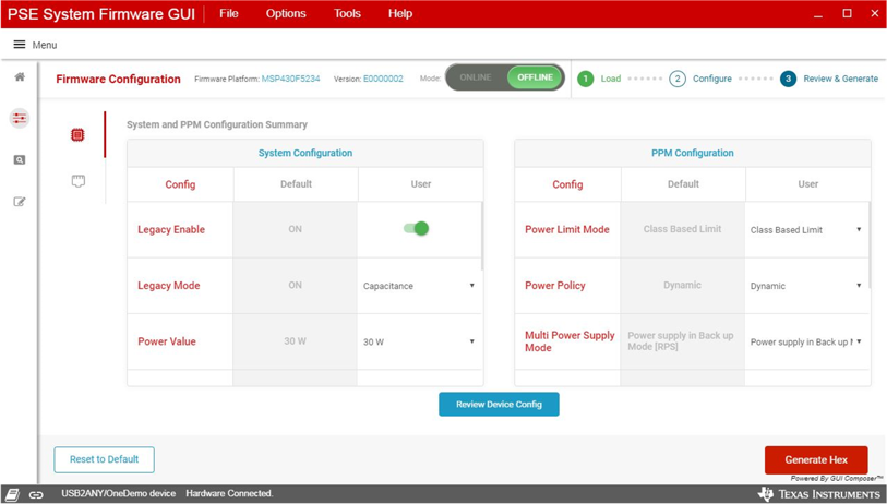
When everything has been configured, click the Proceed button. The summary page displays all of the configurations being set compared to the factory default configurations. When everything is verified, you can generate the hex file or flash the code to the MSP430 device directly.
When configurations are reviewed, the GUI can generate the default code image and program the device directly through MSP-FET.
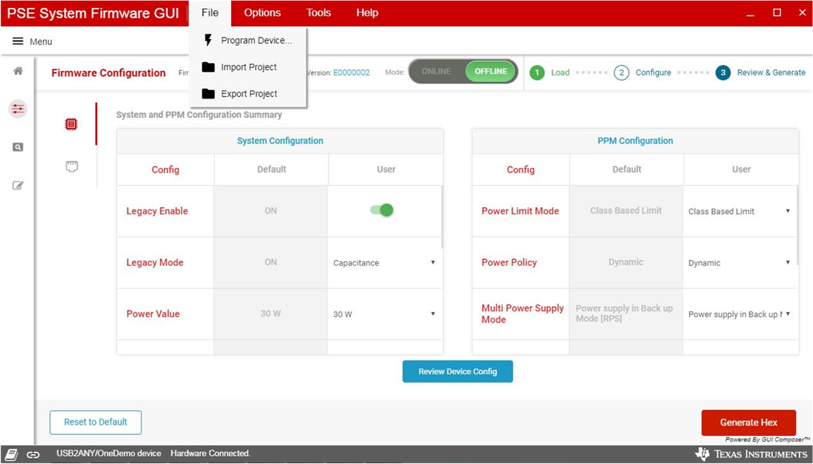
When the code is successfully flashed to the MSP430, the system will be up and running. MSP-FET can be disconnected from the laptop or PC. Connect the USB2ANY (with 30-pin ribbon cable) to a laptop or PC and the GUI will be in online mode after selecting host interface protocol.
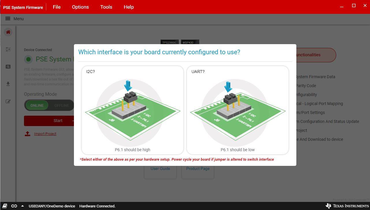
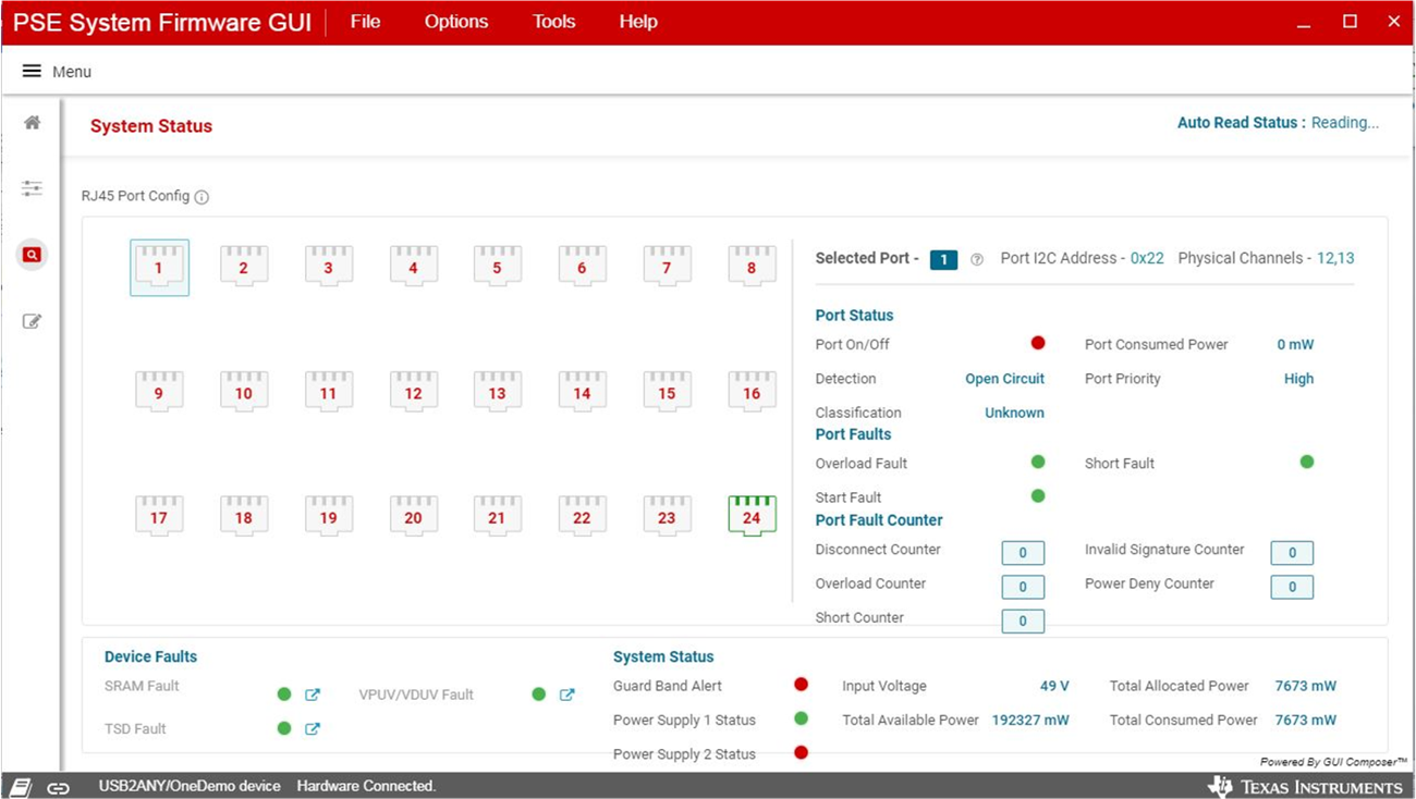
When the device is connected to GUI, real-time changes can be made on the configuration page and status page shows the real time system status. The status page shows the system, device, and port real-time status. The user can also change the system configuration in the configuration page: each change is converted to a host command to the MSP430 MCU. The user can also press the Save Configuration button to save the current configuration as the default setting.
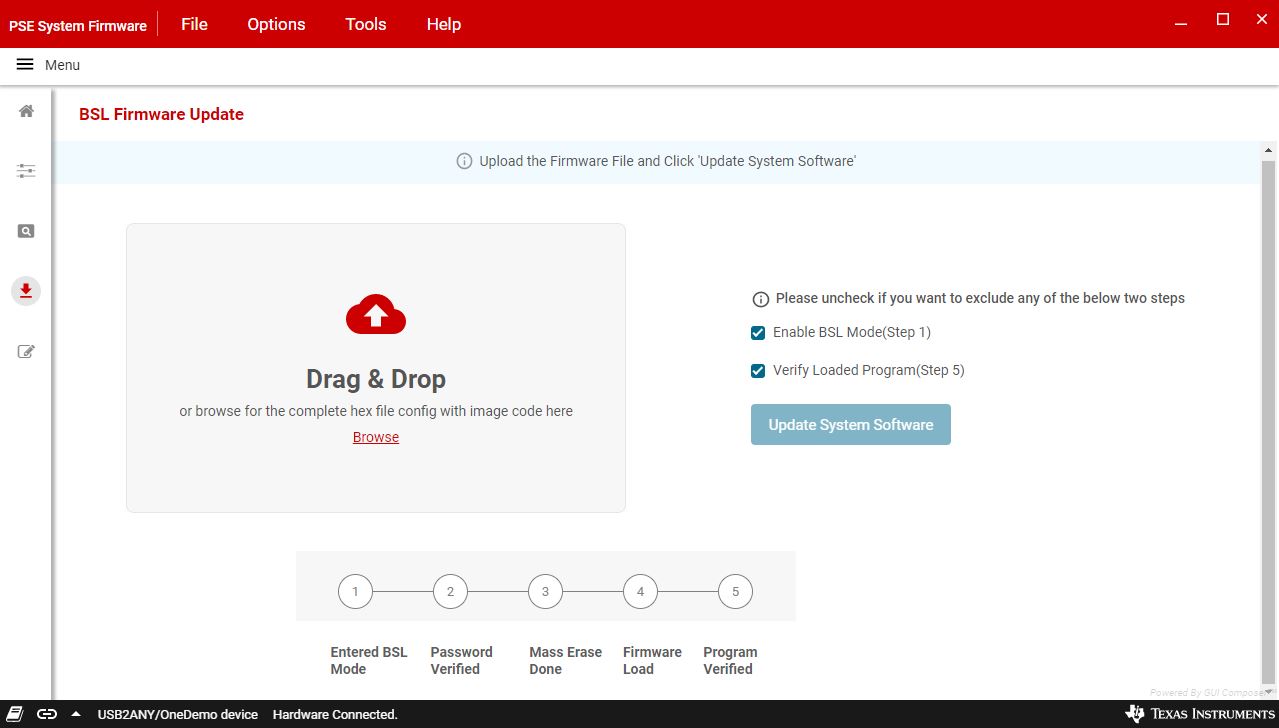
The BSL firmware update page provides the field firmware upgrade functions that the firmware can be upgraded through the same I2C or UART port as the normal communication. This is beneficial to firmware upgrade after the product is released to customers.
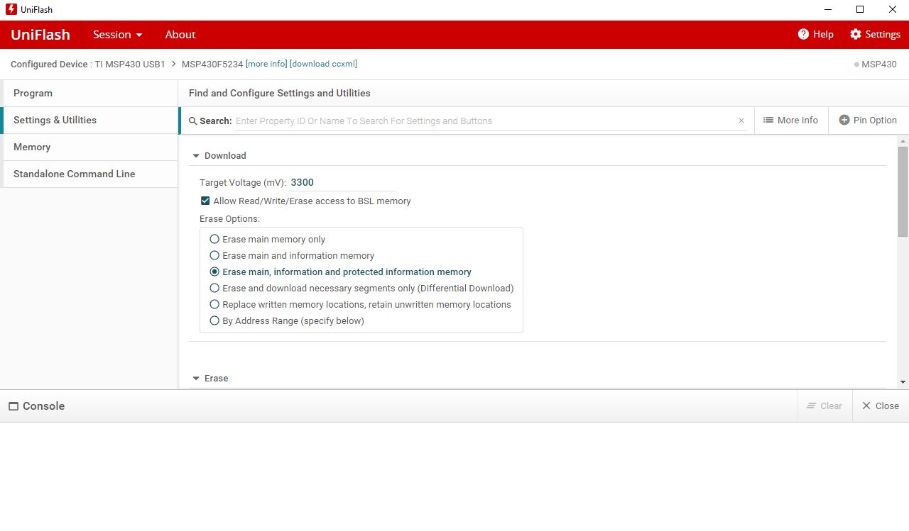
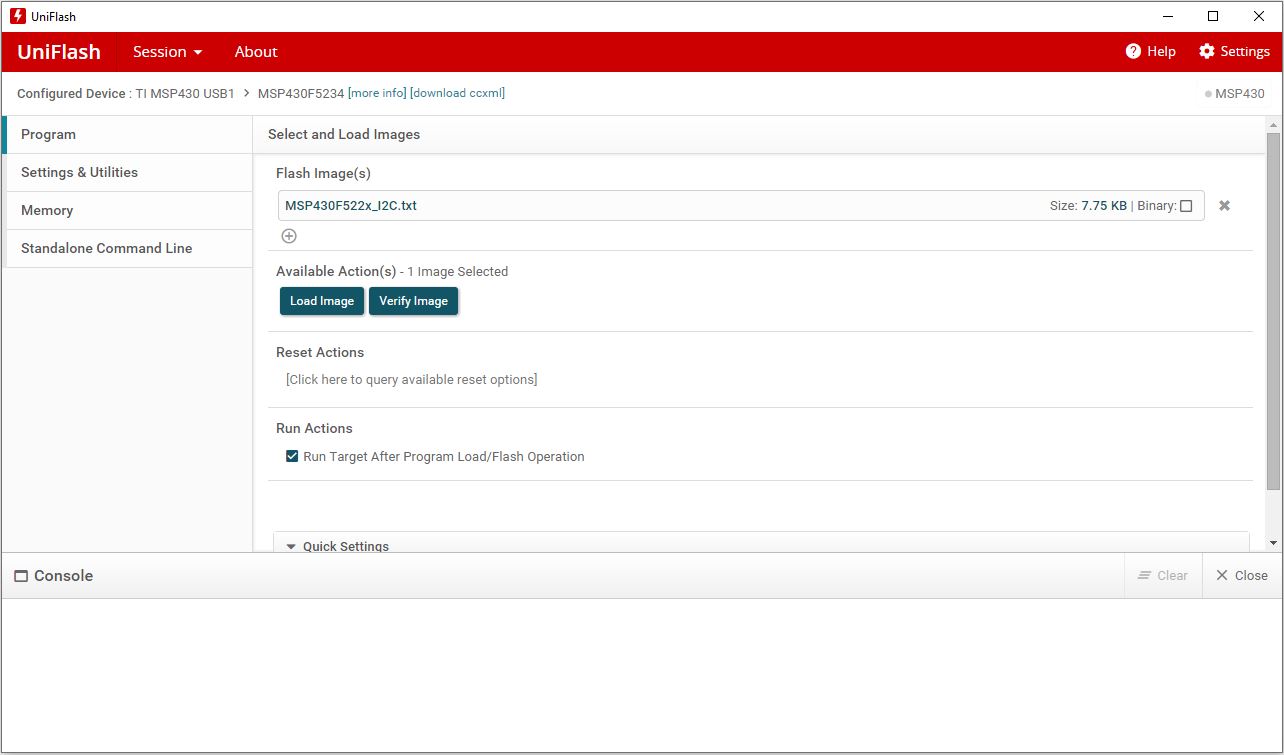
Before using BSL page to update the MSP430 firmware, BSL code needs to be flashed to MSP430 if it hasn't been flashed. Download Uniflash from ti.com and use it to flash the BSL code by following the steps:
Select MCU device to MSP430F5234.
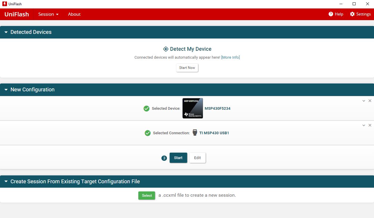
Configure the flash section.
Load BSL code and flash to MSP430.
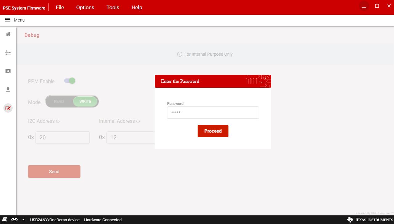
In the debug page, user's can read and write raw data to MSP430 following host interface protocol and to each PSE device's registers by providing I2C address and register number. The password is "C430".
