TIDUEM7A April 2019 – February 2021
- Description
- Resources
- Features
- Applications
- 5
- 1System Description
-
2System Overview
- 2.1 Block Diagram
- 2.2 Highlighted Products
- 2.3 Design Considerations
- 2.4
Hardware, Software, Testing Requirements, and Test Results
- 2.4.1 Required Hardware and Software
- 2.4.2
Testing and Results
- 2.4.2.1 Test Setup
- 2.4.2.2 Test Results
- 3Design Files
- 4Related Documentation
- 5About the Author
- 6Revision History
2.3.2.1 ADS131M04 Current-Detection Procedure
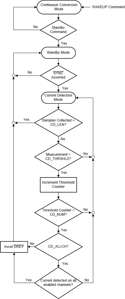
Figure 2-7 shows the details of the procedure followed by the ADS131M04 device to enter current-detection mode as well as the procedure followed when in this mode.
 Figure 2-7 ADS131M04 Current-Detection Mode Process
This process begins by the MCU sending a standby command to the ADS131M04 device from its normal continuous conversion mode. By sending this command, the ADS131M04 device is put in standby mode. Note that the DRDY pin should not be asserted every time a new sample is available, like it was when the device was in normal conversion mode. The DRDY pin is only asserted low when in current-detection mode if tamper current is detected. In addition, the DRDY pin is not asserted low in standby mode since the device is not converting samples.
After the device is in standby mode, provide a pulse on the SYNC/ RESET pin, which enables the device to enter current-detection mode, assuming the CD_EN bit is already enabled in the corresponding ADS131M04 register. When in current-detection mode, the ADS131M04 checks to see if the absolute value of each sample is above the user-defined threshold, which is set by the CD_THRSHLD registers. If a sample is beyond the set threshold, a threshold counter for this current sampling window is incremented. After this threshold is incremented, a check is done to see if the threshold counter is above the value set by the CD_NUM bits in the corresponding ADS131M04 register. The CD_NUM bits configure the number of samples which need to exceed the threshold (CD_THRSHLD) for detection to occur. The purpose of requiring multiple samples for detection is to allow for noisy values that may exceed the threshold, but do not represent a high enough power level to warrant action by the host. If the threshold counter is greater than the value set by the CD_NUM bits, DRDY is asserted if the CD_ALLCH bit in the ADS131M04 register is set to 0 or if the CD_ALLCH bit is set to 1 and current is detected on all enabled channels. After DRDY is asserted, the device goes back to standby mode even if a full sample window has not been checked yet. If the number of samples checked equals the sample window, which is set by the CD_LEN bits in one of the ADS131M04 registers, and the threshold counter is not above CD_NUM, the device goes back to standby mode without DRDY having been asserted.
Figure 2-8 shows two example scenarios of running current-detection mode. In Figure 2-8, more than CD_NUM number of samples are not beyond the current-detection threshold for the first time current-detection mode is triggered. As a result, the ADS131M04 device is in current-detection mode for the maximum time period. For the second time current-detection mode is triggered, more than CD_NUM number of samples are beyond the current-detection threshold, which may indicate tampering has occurred. Immediately after more than CD_NUM samples are beyond the current-detection threshold, the ADS131M04 alerts the MCU and then exits current-detection mode instead of continuing in current-detection mode until the CD_LEN number of samples has been obtained. As a result, the time spent in current-detection mode is smaller the second time the current-detection mode is triggered in this example compared to the first time current-detection mode was triggered.
 Figure 2-8 ADS131M04 Current Detection Example