TIDUEM7A April 2019 – February 2021
- Description
- Resources
- Features
- Applications
- 5
- 1System Description
-
2System Overview
- 2.1 Block Diagram
- 2.2 Highlighted Products
- 2.3 Design Considerations
- 2.4
Hardware, Software, Testing Requirements, and Test Results
- 2.4.1 Required Hardware and Software
- 2.4.2
Testing and Results
- 2.4.2.1 Test Setup
- 2.4.2.2 Test Results
- 3Design Files
- 4Related Documentation
- 5About the Author
- 6Revision History
2.3.1.1 TPS7A78 Cap-Drop Supply
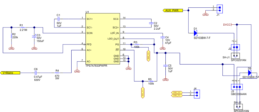
This design uses a TPS7A78 device to create a cap-drop supply with a larger maximum output current than conventional cap-drop LDO-based power supplies without using magnetic components. Figure 2-3 shows the circuit used in this design to implement the cap-drop supply. The TPS7A78 120-mA, Smart AC/DC Linear Voltage Regulator data sheet has details on how to select the optimal values of the components shown in Figure 2-3 for various system requirements.
 Figure 2-3 TPS7A78 Cap-Drop Supply Circuit
In Figure 2-3, capacitor C6 is the high-voltage capacitor that determines the maximum output current possible with this cap-drop supply. Resistor R4 is a resistor that is used to limit the inrush current to the TPS7A78 device. This resistor can be used to protect the device from surge currents in conjunction with transient voltage suppressor (TVS) or a metal-oxide varistors (MOV). If the design is selected to be referenced with respect to neutral, "V+Mains" in Figure 2-3 is connected to the line through resistor R29 (shown in Figure 2-4), and GND is connected to the neutral through resistor R37 (also shown in Figure 2-4). If the design and shunt is selected to be referenced with respect to line instead, GND in Figure 2-3 is connected to the line through resistor R29 (shown in Figure 2-4) and "V+Mains" is connected to the neutral through resistor R37 (also shown in Figure 2-4). In this design, note that R29 and R37 can be replaced with ferrite beads for EMI suppression instead of using the 0-Ω resistors currently populated in the design.
The TPS7A78 device uses an internal active clamp instead of using the external Zener diodes typically used in traditional cap-drop supplies. In addition, the device uses a 4:1 switch-cap stage that divides the clamped voltage by 4, which multiplies the current by 4. As a result, you are able to get a larger output current than conventional cap-drop supplies without having to use magnetic components. The larger output current from the TPS7A78 enables getting more output current from the same capacitor size used in a conventional cap-drop supply, or decreasing the capacitor size to get the same maximum output current as a conventional cap-drop supply, or both. The increased output current allowed by a TPS7A78-based cap-drop supply enables the maximum output current from the power supply to be designed so that it is sufficiently greater than the maximum current consumption of the system, which ensures that the cap-drop supply can still power the meter, even if the value of the capacitor decreases slightly over time. In this design, a 470-nF capacitor is used, which allows powering loads up to 50 mA.
The TPS7A78 device also has an integrated power-fail indication that can be used for an alert of a potential power outage so that the MCU can take any final actions. The power fail indication is done at the input of the switch-cap stage, which allows an early detection of a power failure. The power failure threshold is set using a resistor divider between the SCIN pin, PFD pin, and ground of the TPS7A78 device. In this design, this power failure indication is used to put the ADS131M04 device in current-detection mode before the system is switched to being powered from the backup supply. This design has support for a backup supply, such as a battery, by connecting the negative terminal of the backup supply to pin 2 of J1 in Figure 2-3 and its positive terminal to pin 1 of J1. If a backup power supply is used in this design, an OR of the TPS7A78 output and the backup battery has to be implemented, which can be done with diodes D1 and D9, as Figure 2-3 shows. Note that using diodes to OR the two power supplies results in a voltage drop; however, to reduce the effect of a reduced output voltage, the 3.3-V TPS7A7833 variant used in this design can be replaced with the higher voltage TPS7A7836 3.6-V variant to offset the drop-in voltage from the diode. In this design, it is assumed that the TPS7A78 output voltage is higher than the voltage of the backup supply so that the design is powered from the TPS7A78 when AC Mains is available. If the voltage of the backup supply was larger than the TPS7A78 device, then the design is powered from the backup supply even if AC Mains is available.
In addition to a power-failure indication, the TPS7A78 device has a power good indication, which is asserted when the voltage at the output of the LDO is greater than 90% of the desired LDO output voltage. This power good indication is used to inform the system when power has returned after an outage, which alerts the MCU to tell the ADS131M04 to exit current-detection mode. The TPS7A78 also integrates an LDO on the output stage of the switched cap to regulate VOUT and attenuate ripple.
The reduced capacitor size allowed by the TPS7A78 and the TPS7A78 integrated active clamp, integrated LDO, integrated power failure indication, and integrated power good indication reduces the PCB size taken by this cap-drop supply compared to conventional cap-drop supplies.