TIDT228 October 2022
3.2 Output Voltage Ripple
Output voltage ripple at 115VAC, 60Hz input is shown in the following figures. The output ripple voltage is sub-modulated by the burst frequency at lighter loads.
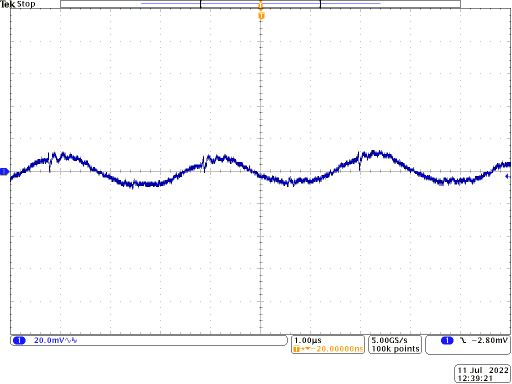 Figure 3-5 20-V Output With 3-A Load
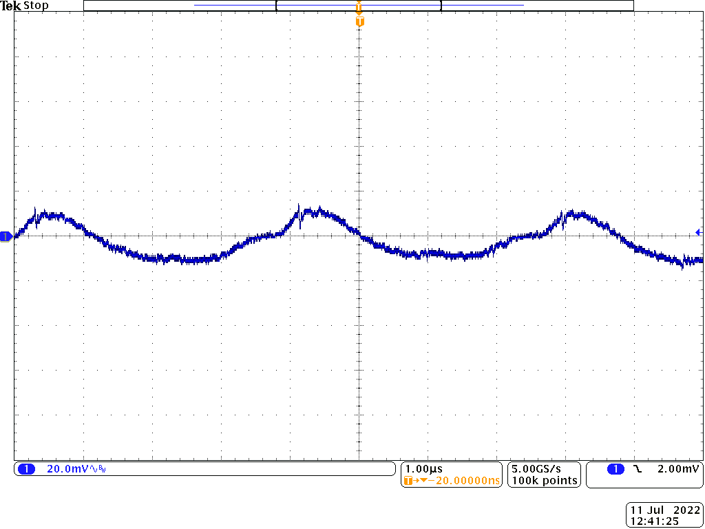 Figure 3-7 15-V Output With 4-A Load
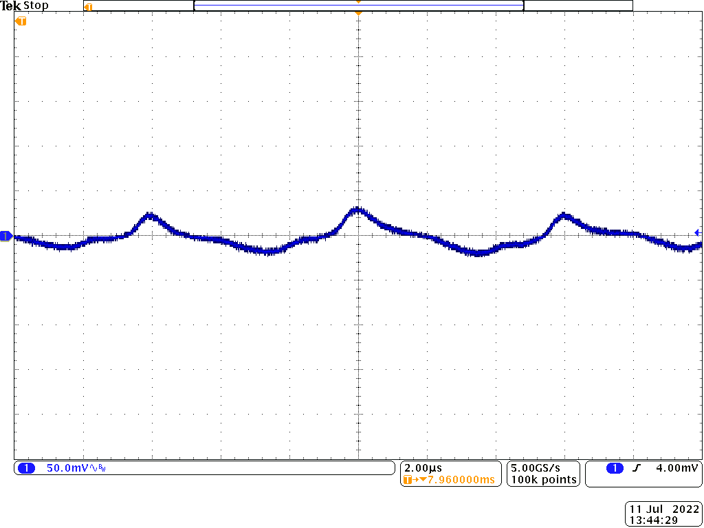 Figure 3-9 9-V Output With 6-A Load
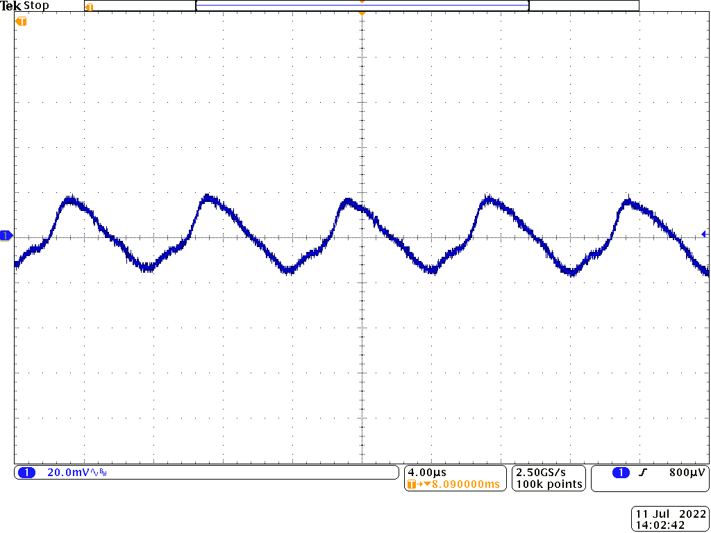 Figure 3-11 5-V Output With 6-A Load
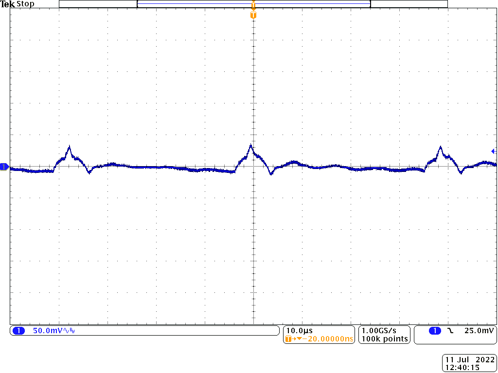 Figure 3-6 20-V Output With 250-mA Load
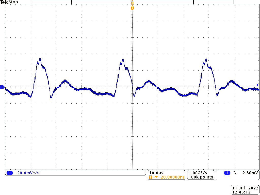 Figure 3-8 15-V Output With 400-mA Load
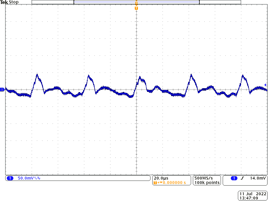 Figure 3-10 9-V Output With 600-mA Load
 Figure 3-12 5-V Output With 1-A Load