SWRU558 June   2020 CC3100 , CC3100MOD , CC3200 , CC3200MOD


  1.   SimpleLink Wi-Fi CC3100, CC3200 UniFlash
    1.     Trademarks
    2. Introduction
      1. 1.1 Overview
    3. Installation
      1. 2.1 Linux
        1. 2.1.1 Limitations
        2. 2.1.2 During Installation
        3. 2.1.3 Running UniFlash
        4. 2.1.4 C++ Dependencies
        5. 2.1.5 COM Port
        6. 2.1.6 Porting Between Windows and Linux
    4. Prerequisites
      1. 3.1 Software
      2. 3.2 Hardware
    5. Uniflash Block Diagram
    6. Session Support
      1. 5.1 Overview
      2. 5.2 Session Conversion
      3. 5.3 Creating a Session
        1. 5.3.1 Session Content
        2. 5.3.2 Creation Procedure
        3. 5.3.3 Relative Path Support
      4. 5.4 Saving a Session
      5. 5.5 Loading a Session
    7. Secured File System Support
    8. GUI Interface
      1. 7.1 Main Screen
      2. 7.2 Target Connection
      3. 7.3 Format
      4. 7.4 Get Version
      5. 7.5 File Programming
        1. 7.5.1 General
        2. 7.5.2 Non-Secured File Programming
        3. 7.5.3 Secured File Programming
      6. 7.6 Service Pack Programing
        1. 7.6.1 General
        2. 7.6.2 Procedure
      7. 7.7 Adding a New File to the Device
      8. 7.8 Erasing Existing File From the Device
      9. 7.9 Removing Existing File From the Template
    9. CC3200 Support
      1. 8.1 Overview
      2. 8.2 Configuration and Programing
    10. Command Line Support
      1. 9.1 Overview
      2. 9.2 Programming
        1. 9.2.1 Command Line Syntax
        2. 9.2.2 Help Manual
      3. 9.3 Available Options
        1. 9.3.1 Available Operations
        2. 9.3.2 Legend
        3. 9.3.3 Programming Example
    11. 10 Configuration File Support
      1. 10.1 Overview
      2. 10.2 Configuration Groups – Parameters’ Description
        1. 10.2.1 Device Role
        2. 10.2.2 Station
        3. 10.2.3 Access Point (AP)
        4. 10.2.4 Peer 2 Peer (P2P)
        5. 10.2.5 Profiles
        6. 10.2.6 HTTP Server
        7. 10.2.7 DHCP Server
        8. 10.2.8 mDNS Client
        9. 10.2.9 Smart Config
      3. 10.3 Configuration Groups – GUI Interface
        1. 10.3.1 Device Role
          1. 10.3.1.1 Restore to Default
          2. 10.3.1.2 Programming
          3. 10.3.1.3 Generation of Binary Templates
          4. 10.3.1.4 Configuration
        2. 10.3.2 Station
          1. 10.3.2.1 Restore to Default
          2. 10.3.2.2 Programming
          3. 10.3.2.3 Generation of Binary Templates
          4. 10.3.2.4 Flow
          5. 10.3.2.5 Configuration
        3. 10.3.3 Access Point (AP)
          1. 10.3.3.1 Restore to Default
          2. 10.3.3.2 Programming
          3. 10.3.3.3 Generation of Binary Templates
          4. 10.3.3.4 Flow
          5. 10.3.3.5 Configuration
        4. 10.3.4 Peer 2 Peer (P2P)
          1. 10.3.4.1 Restore to Default
          2. 10.3.4.2 Programming
          3. 10.3.4.3 Generation of Binary Templates
          4. 10.3.4.4 Flow
          5. 10.3.4.5 Configuration
        5. 10.3.5 HTTP Server
          1. 10.3.5.1 Restore to Default
          2. 10.3.5.2 Programming
          3. 10.3.5.3 Generation of Binary Templates
          4. 10.3.5.4 Flow
          5. 10.3.5.5 Configuration
        6. 10.3.6 DHCP Server
          1. 10.3.6.1 Restore to Default
          2. 10.3.6.2 Programming
          3. 10.3.6.3 Generation of Binary Templates
          4. 10.3.6.4 Flow
          5. 10.3.6.5 Configuration
        7. 10.3.7 mDNS Client
          1. 10.3.7.1 Restore to Default
          2. 10.3.7.2 Programming
          3. 10.3.7.3 Generation of Binary Templates
          4. 10.3.7.4 Adding/Deleting a Service
          5. 10.3.7.5 Flow
          6. 10.3.7.6 Configuration
        8. 10.3.8 Profiles
          1. 10.3.8.1 Restore to Default
          2. 10.3.8.2 Programming
          3. 10.3.8.3 Generation of Binary Templates
          4. 10.3.8.4 Adding/Deleting a Profile
          5. 10.3.8.5 Flow
          6. 10.3.8.6 Configuration
        9. 10.3.9 Smart Config
          1. 10.3.9.1 Restore to Default
          2. 10.3.9.2 Programming
          3. 10.3.9.3 Generation of Binary Templates
          4. 10.3.9.4 Flow
          5. 10.3.9.5 Configuration
    12. 11 Image Creation and Programming
      1. 11.1 Overview
      2. 11.2 Basic Concept and Operation
      3. 11.3 Image Creation – Supported Commands
        1. 11.3.1 Overview
        2. 11.3.2 General Settings
        3. 11.3.3 Format Storage Command
        4. 11.3.4 Write Service Pack Command
        5. 11.3.5 Write File Command
        6. 11.3.6 Write Gang Image Command
        7. 11.3.7 Start Logger Command
      4. 11.4 Image Creation – GUI Interface
        1. 11.4.1 Image Programming Summary Window
        2. 11.4.2 Image Programming Buttons
          1. 11.4.2.1 Add
          2. 11.4.2.2 Remove
          3. 11.4.2.3 Move
          4. 11.4.2.4 Program
          5. 11.4.2.5 Export
          6. 11.4.2.6 Settings
      5. 11.5 Image Programming to Target
      6. 11.6 How to Build an Image Guide
      7. 11.7 Serial Flash usage and Design
        1. 11.7.1 Overview
        2. 11.7.2 File System Guidelines
        3. 11.7.3 Memory Usage
          1. 11.7.3.1 Device Generic
          2. 11.7.3.2 Image Specific
      8. 11.8 Image Creation – Troubleshooting
    13. 12 Troubleshoot/Debugging
    14. 13 Limitations
    15. 14 References
  2.   A UART Connection
    1.     A.1 UART Connection

How to Build an Image Guide

This section describes the recommended procedure to build a binary image. Before starting, please verify the following checklist:

  • Capacity of the serial flash
  • Location of all user files
  • Desired setup of all configuration files
  • Latest Service Pack binary file

Figure 47 describes the flow that must be followed in order to generate an image.
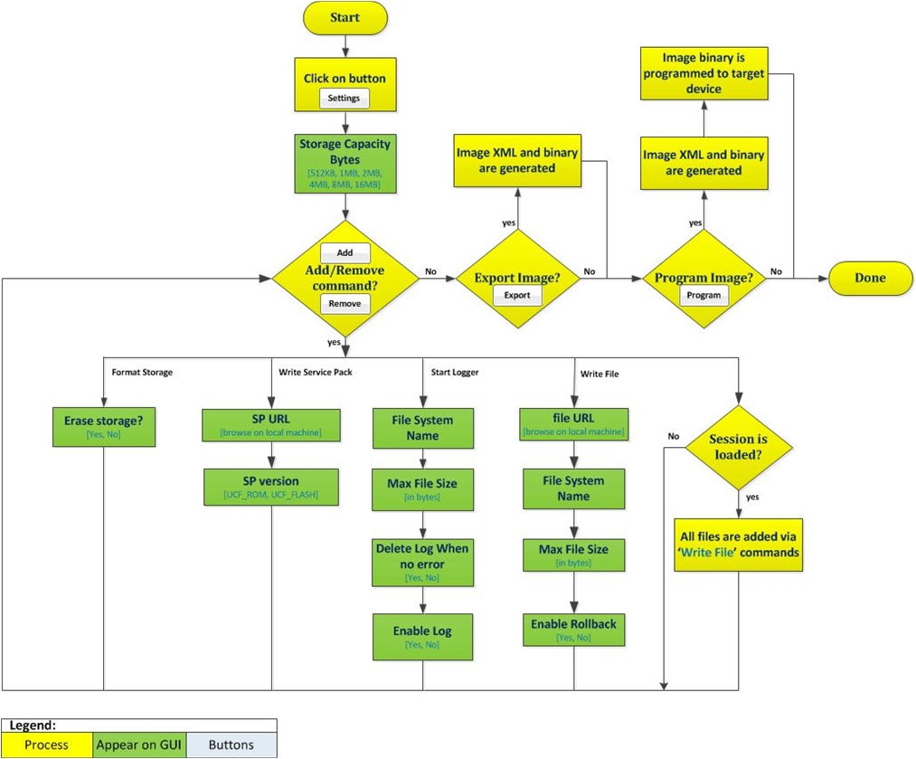
cc3x00-flowchart-07-programming-gui-flow-swru558.jpgFigure 47. Programming GUI Flow

The recommended steps to build the image:

  1. Build a session and include the following files:
    1. System files: by configuring any system file from the System Files group.
    2. Configuration files: by configuring the desired Configuration Groups and checking their respective Update checkbox.
    3. User files: by manually adding files via the Add File button.
  2. Save the session.
  3. Go to Gang Programming group.
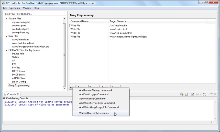
  4. Import the session into the Gang Programming window by clicking AddWrite all files in the session option and then pick the *.usf session you created. All files should be imported into the window.
  5. cc3x00-gui-20-import-session-swru558.jpgFigure 48. Import Session
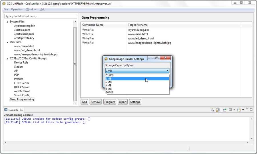
  6. Click on Settings button and configure the Storage Capacity Bytes from the drop down window.
  7. cc3x00-gui-18-general-settings-swru558.jpgFigure 49. General Settings
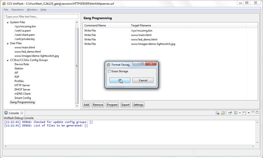
  8. Add a format command by clicking the Add → Add Format Storage Command. This step is mandatory as it creates the FAT table.
  9. cc3x00-gui-13-add-format-swru558.jpgFigure 50. Add Format
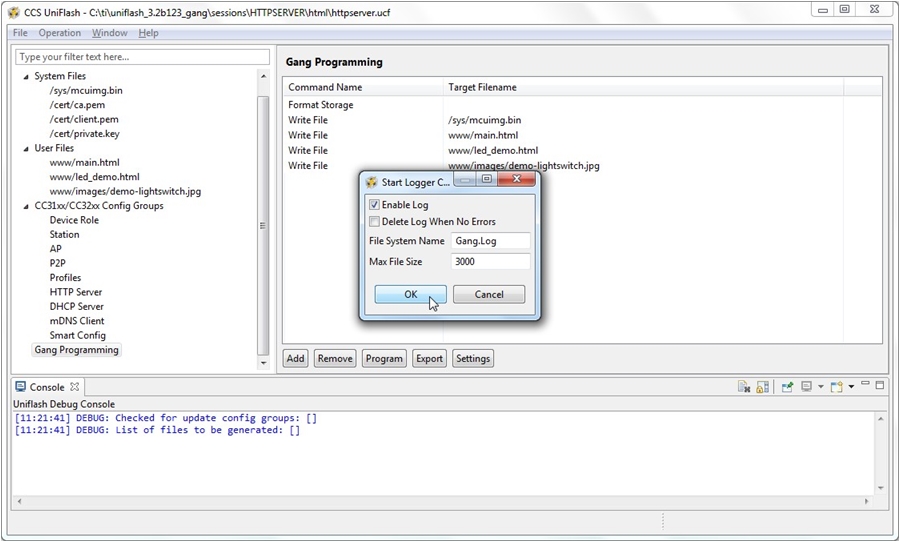
  10. It is optional to add logging during image extraction. It can be done by clicking the Add → Add Start Logger Command. It is recommended mainly in development phase and not during production line.
  11. cc3x00-gui-14-add-logger-swru558.jpgFigure 51. Add Logger
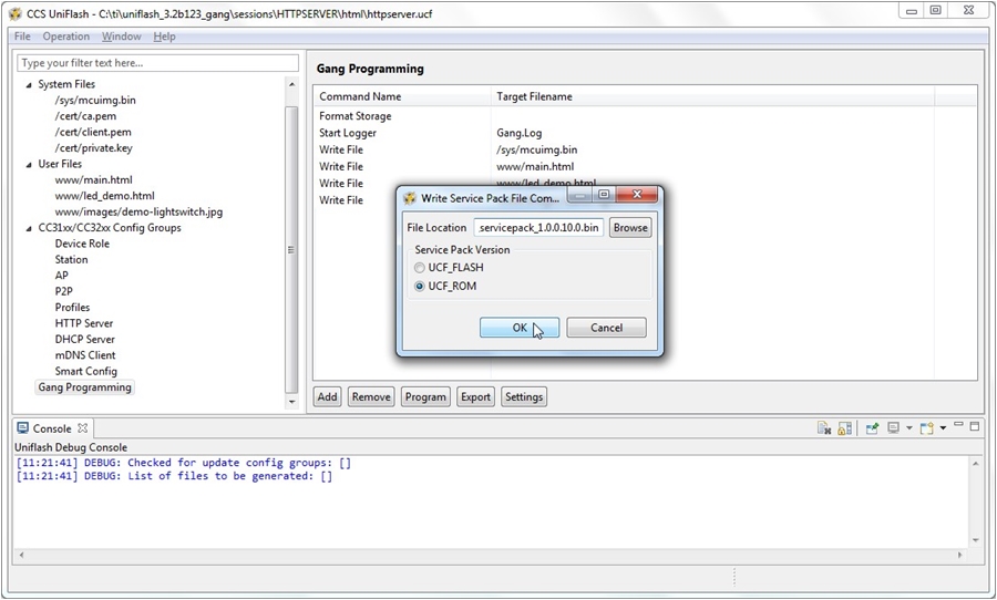
  12. Add the Service Pack. This step is also mandatory as the device gets formatted and the latest Service Pack should be used. It can be done by clicking the Add → Add Write Service Pack Command.
  13. cc3x00-gui-15-add-service-pack-swru558.jpgFigure 52. Add ServicePack
  14. Export to create the binary image or Program to create and program the binary image.
  15. cc3x00-gui-16-export-swru558.jpgFigure 53. Export
  16. Make sure you get no errors on the Console window. You should get the Finished Successfully message and the total amount of required blocks as shown in Figure 53.
  17. Reset the device. Upon initialization, the device extracts the binary image and executes the command, one-by-one. If the procedure is successful, SimpleLink device sends the initialization complete event.