SPRUJ22A November 2021 – March 2023 AWR2944
- Trademarks
- 1Getting Started
-
2Hardware
- 2.1 Block Diagram
- 2.2 PCB Handling Recommendations
- 2.3 Power Connections
- 2.4
Connectors
- 2.4.1 MIPI 60-Pin Connector (J19)
- 2.4.2 Debug Connector-60 pin (J7)
- 2.4.3 CAN-A Interface Connector (J3)
- 2.4.4 CAN-B Interface Connector (J2)
- 2.4.5 Ethernet Ports (J4 and J9)
- 2.4.6 USB Connectors (J8, J10)
- 2.4.7 OSC_CLKOUT Connector (J14)
- 2.4.8 PMIC SPI Connector (J16) (DNP)
- 2.4.9 Voltage Rails Ripple Measurement Connectors (J1, J5) (DNP)
- 2.5 Antenna
- 2.6 PMIC
- 2.7 On-Board Sensors
- 2.8 PC Connection
- 2.9 Connecting the AWR2944EVM to the DCA1000 EVM
- 2.10 Jumpers, Switches, and LEDs
- 3Design Files and Software Tools
- 4Revision History
2.4.5 Ethernet Ports (J4 and J9)
The AWR2944EVM supports two RGMII Ethernet ports to provide the connection to the network. The J4 connector provides access over a MATEnet port (9-2304372-9 connector) via a DP83TC812R-Q1 PHY. The J9 port provides access over an RJ45 port via a DP83867ERGZR PHY. By default, the RGMII interfaces are connected to the J9 port only. To access the RGMII interface, over the J4 connector several resistors must be populated. For more details please see Section 2.4.5.1 and refer to the Schematic, BOM, and Assembly and Database and Layout sections.
This RGMII interface is intended to operate primarily as a 100Mbps ECU interface and can also be used as an Instrumentation Interface.
The RGMII interface supports following features:
- Full Duplex 10Mbps/100Mbps wire rate Interface to Ethernet PHY over RGMII, parallel interface
- MDIO Clause 22 and 45 PHY management interface
- IEEE 1588 Synchronous Ethernet support
The Ethernet port is interfaced to the AWR2944 through the Ethernet PHY and is used to stream the captured data over the network to the host PC.
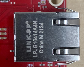
Figure 2-9 shows the Ethernet RJ45 Mag-Jack connector, and Table 2-5 provides the connector pin details.
| Pin Number | Description | Pin Number | Description |
|---|---|---|---|
| 1 | GND | 2 | Test point |
| 3 | ETH_D4P | 4 | ETH_D4N |
| 5 | ETH_D3P | 6 | ETH_D3N |
| 7 | ETH_D2P | 8 | ETH_D2N |
| 9 | ETH_D1P | 10 | ETH_D1N |
| 11 | LED_ACTn | 12 | GND |
| 13 | GND | 14 | LED_LINKn |
| 15 | ETH_GND | 16 | ETH_GND |
 Figure 2-9 RJ45 Connector
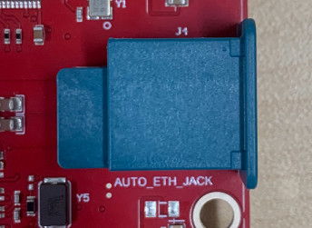
Figure 2-10 shows the Ethernet MATEnet connector, and Table 2-6 provides the connector pin details.
| Pin Number | Description | Pin Number | Description |
|---|---|---|---|
| 1 | TRD_P | 2 | TRD_M |
| S1 | GND | S2 | GND |
| S3 | GND | S4 | GND |
| S5 | GND | S6 | GND |
 Figure 2-10 MATEnet Connector