SPRUJ22A November 2021 – March 2023 AWR2944
- Trademarks
- 1Getting Started
-
2Hardware
- 2.1 Block Diagram
- 2.2 PCB Handling Recommendations
- 2.3 Power Connections
- 2.4
Connectors
- 2.4.1 MIPI 60-Pin Connector (J19)
- 2.4.2 Debug Connector-60 pin (J7)
- 2.4.3 CAN-A Interface Connector (J3)
- 2.4.4 CAN-B Interface Connector (J2)
- 2.4.5 Ethernet Ports (J4 and J9)
- 2.4.6 USB Connectors (J8, J10)
- 2.4.7 OSC_CLKOUT Connector (J14)
- 2.4.8 PMIC SPI Connector (J16) (DNP)
- 2.4.9 Voltage Rails Ripple Measurement Connectors (J1, J5) (DNP)
- 2.5 Antenna
- 2.6 PMIC
- 2.7 On-Board Sensors
- 2.8 PC Connection
- 2.9 Connecting the AWR2944EVM to the DCA1000 EVM
- 2.10 Jumpers, Switches, and LEDs
- 3Design Files and Software Tools
- 4Revision History
2.10.1 Switches
The AWR2944EVM contains two switches to mux various interfaces to different connectors on the EVM.
| Reference | Usage | Comments | Image |
|---|---|---|---|
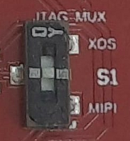
| S1 | JTAG |
When set to ‘MIPI’ position, the JTAG interface is routed to the MIPI 60-pin connector (J19). When set to ‘XDS’ position, the JTAG interface is routed to the XDS110 USB interface (J8) |
 |
| S2 | SPI |
When set to ‘PMIC_SPI’ position, the MSS_SPIB interface is routed to the PMIC and to the J16 header. 1 When set to ‘DBG_SPI’, the MSS_SPIB interface is routed to the 60-pin debug header (J7) |
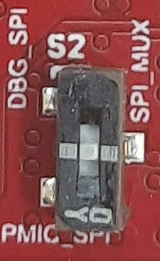 |
- DNP resistors R5, R61, R167, and R176 must be populated to bring the MSS_SPIB interface out to the J16 header.