SNAU252 June   2020 LMK04832-SP


  1.   LMK04832EVM-CVAL User’s Guide
    1.     Trademarks
    2. Evaluation Board Kit Contents
    3. Quick Start
      1. 2.1 Quick Start Description
        1. 2.1.1 Clock Outputs Page Description
        2. 2.1.2 TICS Pro Tips
    4. PLL Loop Filters and Loop Parameters
      1. 3.1 PLL1 Loop Filter
      2. 3.2 PLL2 Loop Filter
    5. Default TICS Pro Mode
    6. Using TICS Pro to Program the LMK04832-SP
      1. 5.1 Start TICS Pro Application
      2. 5.2 Select Device
      3. 5.3 Program the Device
      4. 5.4 Restoring a Default Mode
      5. 5.5 Visual Confirmation of Frequency Lock
      6. 5.6 Enable Clock Outputs
    7. Evaluation Board Inputs and Outputs
    8. Recommended Test Equipment
    9. Length Matching
    10. Schematics
    11. 10 Bill of Materials
  2.   A TICS Pro Usage
    1.     A.1 Communication Setup
    2.     A.2 User Controls
    3.     A.3 Raw Registers Page
    4.     A.4 Set Modes Page
    5.     A.5 Holdover Page
    6.     A.6 CLKinX Control Page
    7.     A.7 PLL1 and 2 Page
    8.     A.8 SYNC / SYSREF Page
    9.     A.9 Clock Outputs Page
    10.     A.10 Other Page
    11.     A.11 Current Calculator Page
    12.     A.12 Burst Page

Current Calculator Page

The Current Calculator page allows the user to also set the same output format register as in the Clock Outputs page, but also set the hardware configuration connected to that output. With this information, along with the other programmed fields a current calculation estimate is made for the LMK04832-SP. Also, power dissipated externally in emitter resistors, and so forth, is estimated and subtracted from the total power to find the IC Power the device must dissipate.

In the lower left is some boxes to account for extra ICC due to LEDs, VCXO, or other.
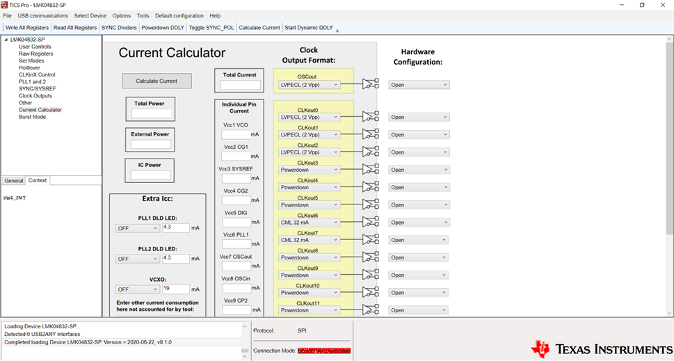
Current_snau252.gifFigure 23. TICS Pro - Current Calculator Page