SLUUCC4A October   2020  – September 2021 TPS92520-Q1


  1.   Trademarks
  2.   General Texas Instruments High Voltage Evaluation (TI HV EMV) User Safety Guidelines
  3. 1Description
    1. 1.1 Typical Applications
    2. 1.2 Warnings
    3. 1.3 Connector Description
  4. 2Performance Specifications
  5. 3Performance Data and Typical Characteristic Curves
    1. 3.1 1.5A CC BUCK SW-Node Voltage Waveform
    2. 3.2 Start-up Waveforms
    3. 3.3 PWM Dimming
  6. 4Schematic, PCB Layout, and Bill of Materials
    1. 4.1 Schematic
    2. 4.2 Layout
    3. 4.3 Bill of Materials
  7. 5Software
    1. 5.1 Demonstration Kit Software Installation for LEDMCUEVM-132 Board
      1. 5.1.1 Installation Overview
    2. 5.2 Step-by-Step Installation Instructions
    3. 5.3 Installation Error Recovery
    4. 5.4 Checking for Updates
  8. 6TPS92520EVM-133 Power Up and Operation
    1. 6.1 Power Up and Operation at VINx < 40 V
    2. 6.2 MCU Control Window
    3. 6.3 SPI Command Window
    4. 6.4 Watchdog Window
    5. 6.5 GUI Devices Window
      1. 6.5.1 Channel 1 or 2 Sub-Window: Settings, Measurements, and Faults
      2. 6.5.2 Device Sub-Window: Shared Device Settings, Measurements, Register Info, and Limp Home
    6. 6.6 Limp Home Mode Window
  9. 7Revision History

MCU Control Window

Run the program LED_Controller_GUI_LP.exe, located at the ":\Texas Instruments\TPS92518, 520, 682 LaunchPad Evaluation Software", to start the GUI. The window shown in Figure 6-7 opens.
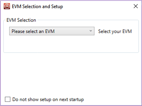
GUID-5C8056B6-F17E-4062-8B6D-553FCC1C3F8C-low.gif Figure 6-7 GUI Setup Screen 1

Click on the EVM selection option to select the TPS92520 - EVM133 - PSIL133.
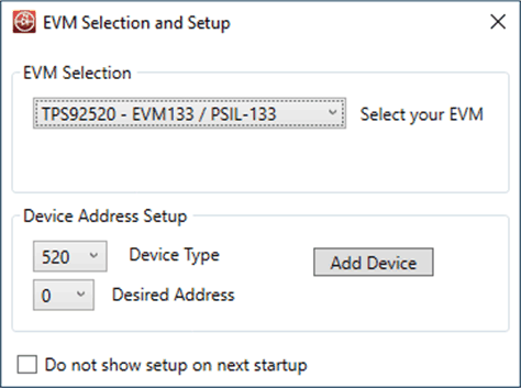
GUID-20200807-CA0I-WQCD-CLR3-XCCTQRNSZCDJ-low.gif Figure 6-8 GUI Setup Screen 2

Select "0 for Desired Address (which is the default jumper setting, but can be changed). Click on Add Device.

The GUI will start up and show 4 separate windows (MCU Control, SPI Command, Watchdog, and Devices), see Figure 6-9.
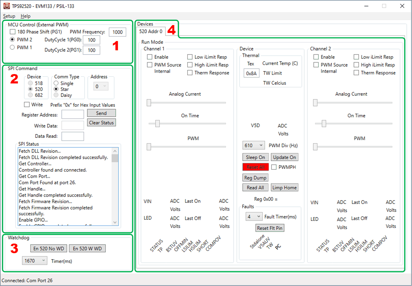
GUID-20200811-CA0I-K1M3-GNB3-HTXJS86ZFHRD-low.gif Figure 6-9 TPS92520 - EVM133 GUI Start-up Screen.
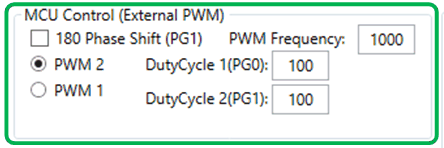
The MCU Control window allows external control of the PWM dimming using the LEDMCUEVM-132 connections to the TPS92520EVM-133. PWM control is available for each channel with frequency and duty cycle control for frequencies and duty cycles that are not covered by the register settings. PWM control also allows for 180 degree phase shift in between channels if desired. For example, if a PWM signal of 4 kHz was desired, they can use this feature.

GUID-20200811-CA0I-KLZP-SLX9-WH7JJJVGMVLN-low.gif Figure 6-10 MCU Control (External PWM) Window.

PWM 1 is the first PWM generator from the MCU and controls Duty Cycle 1 at PF2 pin of MCU and Duty Cycle 2 at PF3 pin of the MCU. PWM 2 is the second PWM generator from the MCU and controls Duty Cycle 1 at PG0 pin of the MCU and Duty Cycle 2 at GP1 pin of the MCU. PWM 1 generator signals connects to PWM1 (PF2) and PWM2 (PF3)on the TPS92520EVM-133 board. Therefore, the PWM 1 button must be selected when using the external that is controlled by the LEDMCUEVM-132.
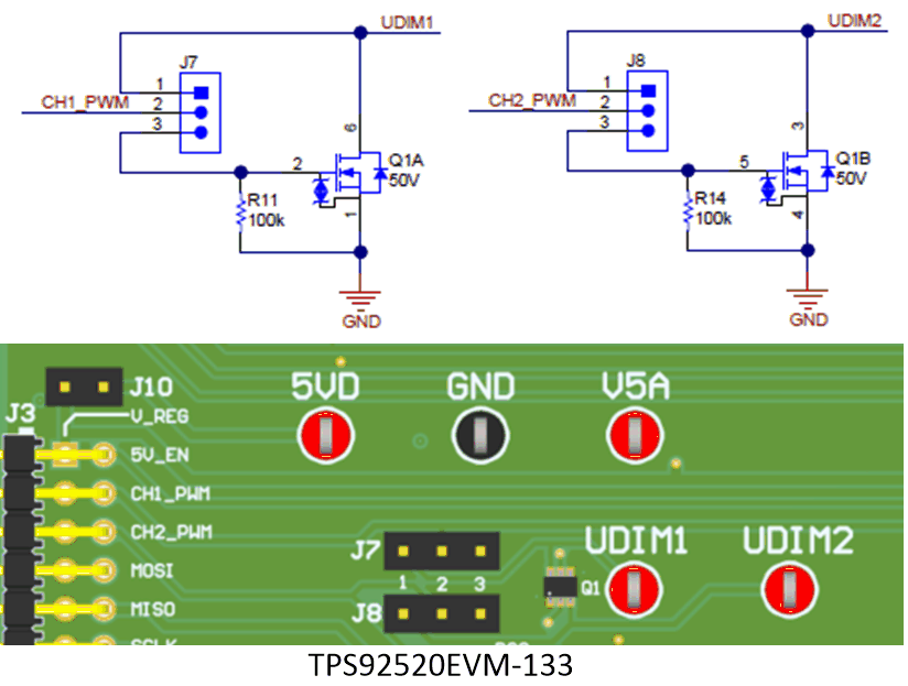
There are two jumpers that need to be selected to use this feature. J7 and J8 are not loaded with shorting jumpers by default and they allow for the direct connection of the external PWM from the LEDMCUEVM-132 by placing a shorting jumper from pins 1 and 2 of J7 and J8. If the inversion of those PWM signals can be achieved by placing a shorting jumper across pins 2 and 3 of J7 and J8, see Figure 6-11.
GUID-20200904-CA0I-PWLM-G2QT-NXTX2TTLPSQ5-low.gif Figure 6-11 External PWM Hardware.