SLAA870 February 2019 AFE7422 , AFE7444
-
Evaluating the frequency hopping capability of the AFE74xx
- Trademarks
- 1 Introduction
- 2 Phase Coherency vs Phase Continuity
- 3 AFE74xx Architecture
- 4 Frequency Hopping Methods
- 5 NCO Frequency Resolution Versus Hop Time
- 6 Fast Frequency Hopping With the Load and Switch
- 7 Register Addresses
- 8 References
2 Phase Coherency vs Phase Continuity
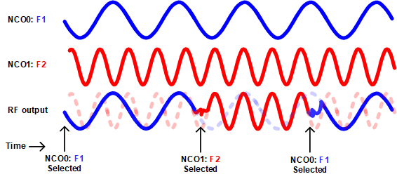
Phase coherency, or phase memory, defines the ability for a synthesizer to maintain phase so that when switching to another source, the original frequency source runs continuously in the background and maintains phase, even when not selected. Therefore, upon returning to the original frequency, the original phase is unaltered. Phase coherency is especially useful in systems where multiple frequency sources use a single reference clock. The overall system may switch sources to reflect the desired frequency source on the RF output, while all other synthesizers run continuously in the background while maintaining phases relative to the reference. Phase-coherent radar systems eliminate the need for recalibration when switching between multiple frequencies because the phase relationship relative to the reference is maintained. Figure 1 shows an example of phase-coherent frequency hopping between NCO0 and NCO1 (programmed to frequencies f1 and f2, respectively), and run continuously, even when not selected.
 Figure 1. Example of Phase Coherent Frequency Hopping
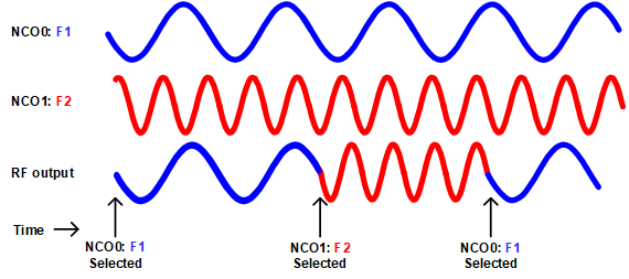
 Phase continuity, however, refers to a smooth and continuous transition from one frequency to another on the RF output when the selected source changes frequencies. Noncontinuous or abrupt transitions in the output frequency may lead to unwanted spurious content during fast Fourier transform (FFT) analysis. Figure 2 shows an example of continuous frequency hopping, where the selected source switches from NCO0 (programmed to F1) to NCO1 (programmed to F2). As seen in Figure 2, when frequency hopping from frequency 1 to frequency 2, there is a continuous transition between frequency 1 and frequency 2.
 Figure 2. Example of Phase Continuous Frequency Hopping