SLAA870 February 2019 AFE7422 , AFE7444
-
Evaluating the frequency hopping capability of the AFE74xx
- Trademarks
- 1 Introduction
- 2 Phase Coherency vs Phase Continuity
- 3 AFE74xx Architecture
- 4 Frequency Hopping Methods
- 5 NCO Frequency Resolution Versus Hop Time
- 6 Fast Frequency Hopping With the Load and Switch
- 7 Register Addresses
- 8 References
4.1 Maintaining Phase Continuity
When updating the output frequency of single RX or TX NCO, phase continuity is maintained using SPI. The programmed frequency is reflected at the receiver or transmitter output only after the newly programmed NCO is reset. NCO reset can occur through SPI, SYSREF, or JESD SYNC signal. For the scope of this application report, both SPI and SYSREF are evaluated as methods for issuing the NCO reset.
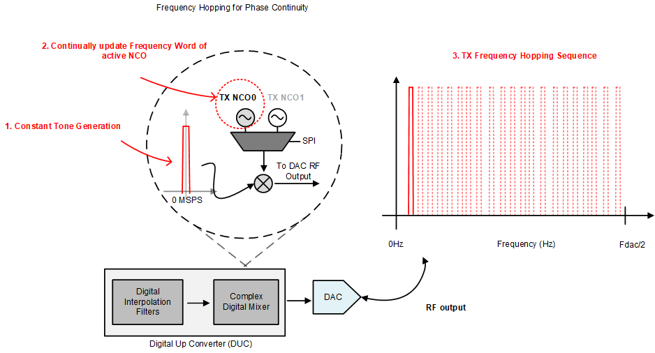
In the following experiments, the hop time is characterized using the AFE74xx transmitter and transmitter NCOs. Phase continuous frequency hopping is implemented using a single TX NCO. The DAC is configured in DDS mode to output a single tone, and The TXNCO0 accumulator word is continually reprogrammed to effectively hop the constant tone output anywhere between 0 Hz and fS / 2, where fS is the sampling frequency. Figure 9 is a visual depiction that shows how phase continuous frequency hopping is implemented with the AFE74xx.
 Figure 9. Implementing Phase Continuous Frequency Hopping With the AFE74xx Evaluation Module (EVM)