DLPU094 July 2020 DLP5530S-Q1
7.3.2.1 Illumination Control Overview
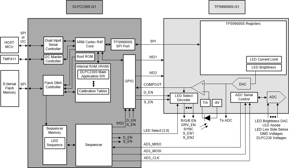
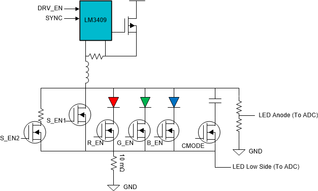
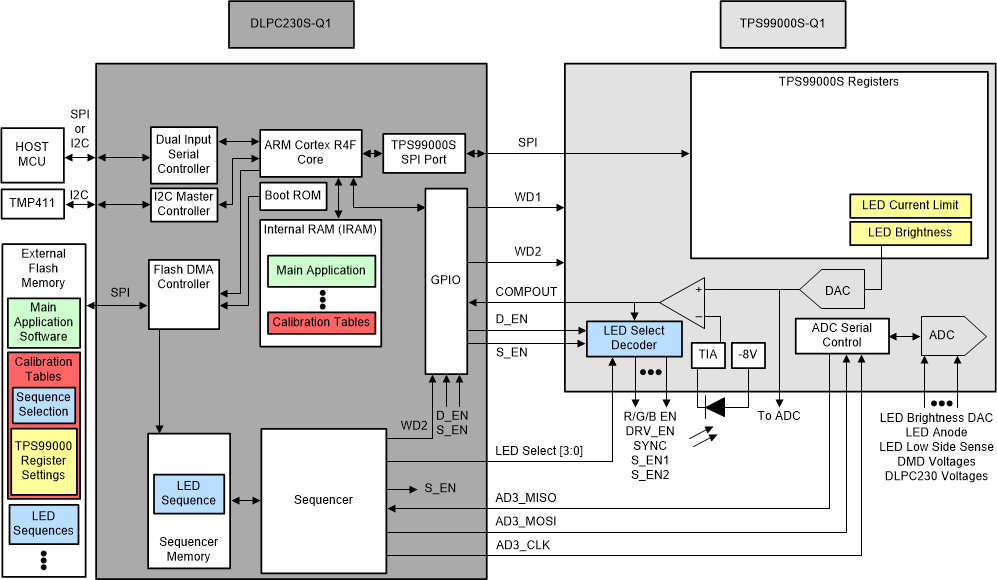
Figure 10 and Figure 11 show the illumination control and LED driver architecture. Figure 12 shows the origin and destination of software, data, and settings.
 Figure 10. Illumination Control Architecture
  Figure 11. LED Driver Architecture
  Figure 12. Software and settings origin and destination
 As seen in Figure 10, Figure 11, and Figure 12:
- At start-up, the Boot ROM commands External Flash to load the Main Application Software and calibration data into the internal RAM (IRAM) of the DLPC230S-Q1. The ARM Core in the DLPC230S-Q1 executes the main application loaded in to the IRAM.
- The host MCU sends dimming commands periodically to the DLPC230S-Q1 to specify the brightness level of the system. At start-up, the calibration data provides a default dimming level.
- Based on the dimming level and calibration data, the DLPC230S-Q1 Software determines the correct LED sequence and TPS99000S-Q1 register settings. The LED sequence is the order and timing of LED pulses. TPS99000S-Q1 register settings determine the brightness of the LED pulses.
- The LED sequence determined by calibration data is requested to be loaded from external flash to the sequencer memory. The sequencer block uses the sequence loaded into its memory to send LED select signals to the TPS99000S-Q1. These signals control the enable and disable for individual LEDs.
- LED brightness is regulated to the level requested by the DLPC230S-Q1 via a feedback loop consisting of the TPS99000S-Q1, LM3409, the LEDs, and a photo-diode. The brightness target is set by the DLPC230S-Q1 into a DAC in the TPS99000S-Q1. LED brightness is measured by a photo-diode and trans-impedance amplifier (TIA) inside the TPS99000S-Q1. The target brightness and the measured brightness are compared by a comparator in the TPS99000S-Q1. The output of the comparator is used for hysteretic control of the LED light level.