TIDUCL3 February 2017
- 1 Overview
- 2 Resources
- 3 Features
- 4 Applications
- 5 Design Images
- 6 System Overview
-
7 System Design Theory
- 7.1 PCB and Form Factor
- 7.2 Optimizing Board Performance Based on LED String Voltage and Current
- 7.3 Switching Frequency
- 7.4 Output Overvoltage Protection (OVP)
- 7.5 Current Monitoring (IMON)
- 7.6 Thermal Foldback
- 7.7 Clock Generation (PWM)
- 7.8 Onboard Supply and Setting Duty Cycle
- 7.9 Buffering, Averaging, and Filtering
- 7.10 Boost Converter
- 8 Getting Started Hardware
- 9 Testing and Results
- 10Design Files
- 11Related Documentation
- 12About the Author
7.6.1.3 Constant Current at High Temperatures
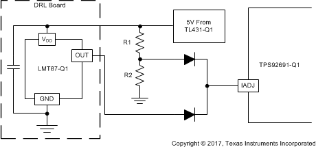
The current design will derate the current according to temperature across the entire temperature range. However, in many applications, thermal foldback needs to clamp the current through the LEDs at a certain point to ensure there is a minimum current through the LEDs regardless of the temperature. This clamp will ensure that the brightness does not decrease past the required minimum brightness as in SAE J1383. The easiest way to achieve this is by diode OR-ing the output voltage from the LMT87-Q1 and a fixed voltage as shown in Figure 13.
 Figure 13. Current Clamp for High Temperatures
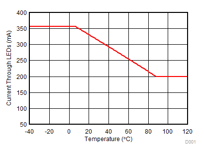
 This would allow the thermal foldback to occur as intended until it reaches a specified threshold where it keeps the current through the LEDs constant. This threshold allows the graph of current versus temperature to look like Figure 14.
 Figure 14. Current versus Temperature With Clamp
 Equation 13 show how to calculate the resistor values needed to clamp at a given current.

Equation 14 shows at what temperature it is going to clamp.
