SWRU372C June   2014  – March 2020 CC3200


  1.   CC3200 SimpleLink™ Wi-Fi® and Internet of Things Solution With MCU LaunchPad™ Hardware
    1. 1 Introduction
      1. 1.1 CC3200 LaunchPad Development Kit
      2. 1.2 Key Features
      3. 1.3 What's Included
        1. 1.3.1 Kit Contents
      4. 1.4 FCC/IC Regulatory Compliance
      5.      Trademarks
    2. 2 Hardware Description
      1. 2.1 Block Diagram
      2. 2.2 Hardware Features
      3. 2.3 Connecting a BoosterPack Plug-in Module
      4. 2.4 Jumpers, Switches, and LEDs
        1. 2.4.1 JTAG Headers
        2. 2.4.2 I2C Connections
          1. 2.4.2.1 Jumper Settings
          2. 2.4.2.2 Default I2C Address
        3. 2.4.3 Power Connections
        4. 2.4.4 UART Signals
        5. 2.4.5 Sense on Power
        6. 2.4.6 Other Miscellaneous
        7. 2.4.7 Push Buttons and LEDs
        8. 2.4.8 2x20 Pin Connector Assignment
      5. 2.5 Power
        1. 2.5.1 USB Power
        2. 2.5.2 Battery Power (2 × 1.5 V)
        3. 2.5.3 BoosterPack Module Power Supply
      6. 2.6 Measure CC3200 Current Draw
        1. 2.6.1 Measuring Low Power (<1 mA)
        2. 2.6.2 Measuring Active Power
      7. 2.7 RF Connections
        1. 2.7.1 Radiated Testing (AP connection)
      8. 2.8 Design Files
        1. 2.8.1 Hardware
        2. 2.8.2 Revision History
        3. 2.8.3 Software
    3. 3 Software Examples
      1. 3.1 Development Environment Requirements
        1. 3.1.1 CCS
        2. 3.1.2 IAR
    4. 4 Additional Resources
      1. 4.1 LaunchPad Kit Wiki
      2. 4.2 Information on the CC3200
      3. 4.3 Download a Development Environment
      4. 4.4 The CC3200 Code Examples
      5. 4.5 CC3200 Application Notes
      6. 4.6 Support Resources
    5. 5 Known Limitations
      1. 5.1 Hardware Limitations
        1. 5.1.1 Floating IO (All Revisions)
        2. 5.1.2 Board Modification for LPDS Mode
        3. 5.1.3 Floating S-Flash Lines (Rev 3.2 and Earlier)
  2.   Revision History

Other Miscellaneous

Table 7. Miscellaneous Settings

Reference Usage Comments
J4 Accelerometer interrupt Short = Route the accelerometer sensor interrupt to the GPIO_13
Open = Isolates the interrupt to the GPIO_13
table_1_other_miscellaneous_swru372.gif
J5 Debug header To observe the network processor (NWP), MAC logs. table_2_other_miscellaneous_swru372.gif
J14 SOP2 isolation Isolate SOP2 (GPIO_25) from the 20-pin connector
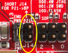
 table_3_other_misc_swru372.png