SWRA578B October   2017  – April 2020 CC1312PSIP , CC1312R , CC1314R10 , CC1352P , CC1352P7 , CC1352R , CC2620 , CC2630 , CC2640 , CC2640R2F-Q1 , CC2642R , CC2642R-Q1 , CC2650MODA , CC2652P , CC2652R , CC2652R7 , CC2652RB , CC2652RSIP


  1.   Ultra-Low Power Sensing Applications With CC13x2/CC26x2
    1.     Trademarks
    2. 1 Overview
    3. 2 Measurement Conditions
      1. 2.1 Software
      2. 2.2 Hardware
    4. 3 Measurements
      1. 3.1 BOOSTXL-ULPSENSE
        1. 3.1.1 Analog Light Sensor
        2. 3.1.2 Capacitive Touch
        3. 3.1.3 LC Flow Meter
        4. 3.1.4 Potentiometer
        5. 3.1.5 Reed Switch
        6. 3.1.6 SPI Accelerometer
      2. 3.2 LPSTK-CC1352R
        1. 3.2.1 I2C Light Sensor
        2. 3.2.2 I2C Temperature and Humidity Sensor
        3. 3.2.3 SPI Accelerometer
        4. 3.2.4 Hall Effect Sensor
      3. 3.3 Comparison with System CPU
        1. 3.3.1 4 MHz SPI Transfer
        2. 3.3.2 1 MHz SPI Transfer
        3. 3.3.3 Wake-up and Sleep
    5. 4 Summary
    6. 5 References
  2.   A Creating the comparison examples
    1.     A.1 SPI Transfer – Sensor Controller
    2.     A.2 SPI Transfer – System CPU
    3.     A.3 Wake Up and Sleep – Sensor Controller
    4.     A.4 Wake up and Sleep – System CPU
  3.   Revision History

SPI Accelerometer

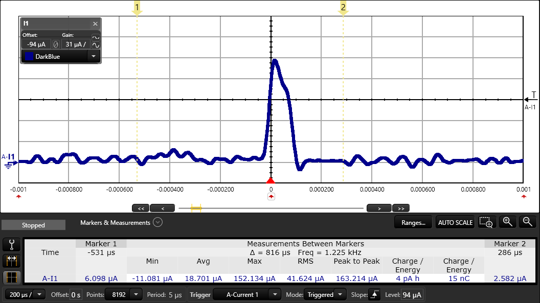
The BOOSTXL-UPLSENSE comes with a ultra-low power accelerometer. This sensor uses the serial peripheral interface (SPI) interface to communicate with the Sensor Controller. In the SPI accelerometer example, the device is kept at a steady state. The accelerometer will report to the Sensor Controller with a frequency of 100 Hz. If a change in the accelerometer over a certain threshold is detected, the Sensor Controller will wake up the system CPU and the System CPU will light up one of two LEDs.

Average Current Consumption Unit
SPI Accelerometer stationary (100 Hz) 5.4 µA
4_1_6 SPI Accelerometer.pngFigure 11. SPI Accelerometer: One Accelerometer Measurement