SWAU085F July 2011 – January 2022
6.4 TX Duty Cycle Configuration
Figure 6-4 shows the Type, Size, Amount, and Delay options (highlighted in red) used to set the duty cycle in the Packets area of the TX tab.
 Figure 6-4 Duty Cycle Control
For best TX performance, TI recommends setting the duty cycle of the device to less than 40% by selecting the correct packet length and delay time for a specific rate.
Equation 1.
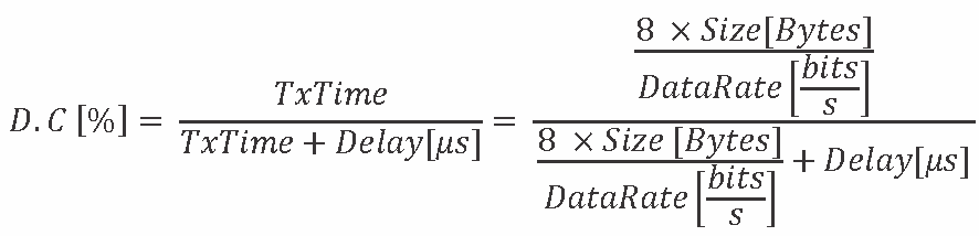
Based on Equation 1, Table 6-2 and Table 6-3 list calculated values for 30% DC at the most common rates.
Table 6-2 20-MHz BW Rates
| Rate | 20-MHz BW | |
|---|---|---|
| Size (Bytes) | Delay (µs) | |
| 1DSSS | 26 | 938 |
| 11CCK | 143 | 700 |
| 54OFDM | 1539 | 583 |
Table 6-3 20-MHz and 40-MHz BW Rates
| Rate | 20-MHz BW | 40-MHz BW | ||
|---|---|---|---|---|
| Size (Bytes) | Delay (µs) | Size (Bytes) | Delay (µs) | |
| MCS0 | 218 | 705 | 429 | 700 |
| MCS7 | 1528 | 467 | 1365 | 280 |
| MCS15 | 1495 | 303 | — | — |