SPRUHW1A June   2014  – October 2021 TMS320F28052-Q1 , TMS320F28052M , TMS320F28052M-Q1 , TMS320F28054-Q1 , TMS320F28054M , TMS320F28054M-Q1


  1. 1Read This First
    1. 1.1 About This Manual
    2. 1.1 Glossary
    3. 1.1 Support Resources
    4.     Trademarks
  2. 1 F2805xM InstaSPIN-MOTION Enabled MCUs
  3. 2InstaSPIN-MOTION Key Capabilities and Benefits
    1. 2.1 Overview
    2. 2.2 FAST Unified Observer
    3. 2.3 SpinTAC Motion Control Suite
      1.      IDENTIFY
      2.      CONTROL
      3.      MOVE
      4.      PLAN
    4. 2.4 Additional InstaSPIN-MOTION Features
  4. 3InstaSPIN-MOTION Block Diagrams
    1.     Scenario 1: InstaSPIN-MOTION Speed Control with FAST Software Encoder
    2.     Scenario 2: InstaSPIN-MOTION Speed Control with a Mechanical Sensor
    3.     Scenario 3: InstaSPIN-MOTION Position Control with Mechanical Sensor and Redundant FAST Software Sensor
  5. 4Application Examples
    1. 4.1 Treadmill Conveyor: Smooth Motion Across Varying Speeds and Loads
    2. 4.2 Video Camera: Smooth Motion and Position Accuracy at Low Speeds
    3. 4.3 Washing Machine: Smooth Motion and Position Accuracy at Low Speeds
      1.      Agitation Cycle
      2.      Spin Cycles
    4. 4.4 InstaSPIN-MOTION Works Over the Entire Operating Range
  6. 5Evaluating InstaSPIN-MOTION Performance
    1. 5.1 Overview
    2. 5.2 Velocity Control Performance: SpinTAC vs PI
      1. 5.2.1 Disturbance Rejection
      2. 5.2.2 Reference Tracking
      3. 5.2.3 Step Response
    3. 5.3 Position Control Performance: SpinTAC vs PI
      1. 5.3.1 Disturbance Rejection
      2. 5.3.2 Reference Tracking
      3. 5.3.3 Step Response
      4. 5.3.4 Inertia Estimation Repeatability
  7. 6Microcontroller Resources
    1. 6.1 CPU Utilization
    2. 6.2 Memory Utilization
    3. 6.3 Security Zones
    4. 6.4 Linker Command File Settings
    5. 6.5 Interfacing FAST ROM Libraries
    6. 6.6 Pin Utilization
    7. 6.7 Consideration of Analog Front-End (AFE) Module
      1. 6.7.1 Routing Current Signals
      2. 6.7.2 Voltage Reference Connection
      3. 6.7.3 Routing Voltage Signals
        1.       A Resources
          1.        B Definition of Terms and Acronyms
            1.         C Revision History

Washing Machine: Smooth Motion and Position Accuracy at Low Speeds

Cycle transitions, changing loads, and environmental disturbances cause significant wear and tear on motors. Automatic, real-time reduction of disturbances can extend the life and performance of motors.

Consider washing machines, for example. Figure 5-1 displays the motion profile for three stages of a standard washing machine. The first stage represents the agitation cycle, rotating between 250 rpm and -250 rpm, repeatedly. The second and third stages represent two different spin cycles. The second stage spins at 500 rpm and the third stage spins at 2000 rpm. This profile was easily created using SpinTAC Plan (documented in the InstaSPIN-FOC and InstaSPIN-MOTION User's Guide).

InstaSPIN-MOTION was applied to a washing machine application. The SpinTAC Plan trajectory planning feature was used to quickly build various states of motion (speed A to speed B) and tie them together with state based logic (see Figure 3-4).

The washing machine application was run twice — once using a standard PI controller and once using LineStream's SpinTAC controller. The data was then plotted against the reference curve for comparison.
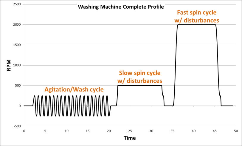
GUID-51215565-EB41-475F-9A50-C71CA5CD069C-low.gifFigure 4-1 Washing Machine Profile