SNLU254A November 2020 – July 2022
3.6 High-Level Page
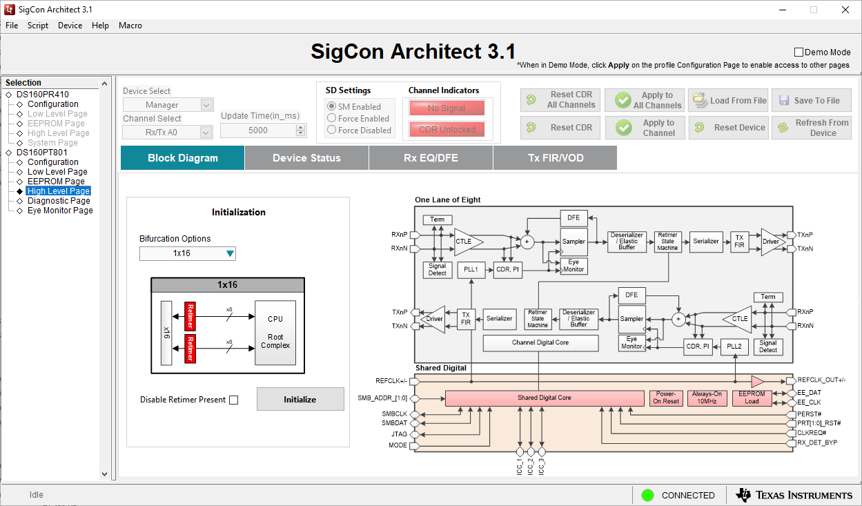 Figure 3-5 High-Level Page
Screenshot
Figure 3-5 High-Level Page
ScreenshotThe High-Level page of the DS160PT801 SigCon Architect GUI provides a user-friendly display of the current status of the retimer along with basic configuration. It contains multiple tabs within the page; the first tab of the page is the Block Diagram, which shows the analog signal components of the DS160PT801 retimer. This page will automatically read the current register link-width setting of the retimer and display it on the left side of the window. The fields that can be used on this page are as follows:
- Bifurcation Options Dropdown allows a user to select from all link width bifurcation options for the PCIe link.
- Disable Retimer Present Checkbox allows the retimer to disable the broadcasting of its presence in the PCIe link over the PCIe protocol.
- Initialize Button applies the Bifurcation and Retimer Present changes to the retimer over SMBus communication. It is important to note than any SMBus settings affecting PCIe link configuration like the link-width will not take effect after a PCIe link has already been established.
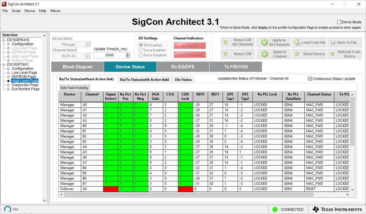 Figure 3-6 High-Level Page – Device
Status Screenshot
Figure 3-6 High-Level Page – Device
Status ScreenshotThe device status tab in the High-Level page have multiple sub-tabs with information about the retimer status. The Rx/Tx status (without Active link) shows status information that does not require an active PCIe link to be valid. This includes receiver detection, signal detection, and equalizer signal conditioning settings.
- Edit Field Visibility Button allows a user to show or hide different columns within the channel status table.
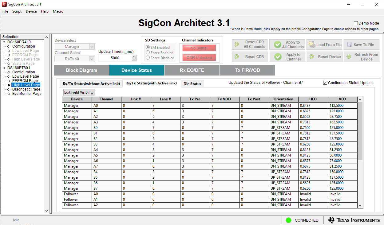 Figure 3-7 High Level Page – Device
Status (Active Link) Screenshot
Figure 3-7 High Level Page – Device
Status (Active Link) ScreenshotAfter a link is established, there are a number of fields that are updated in the retimer to reflect the current status of the PCIe link. This includes the Link, Lane number, and orientation of the data flow.
- Edit Field Visibility Button allows a user to show or hide different columns within the channel status table.
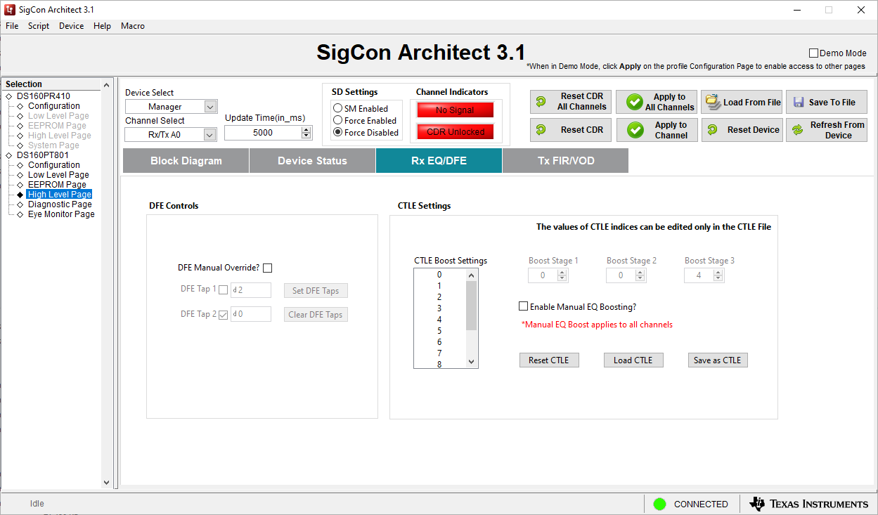 Figure 3-8 High-Level – Rx EQ/DFE
Page
Figure 3-8 High-Level – Rx EQ/DFE
PageThis section of the High-Level page allows a user to force the CTLE settings of the DS160PT801. Both the CTLE and DFE is automatically adaptive by default, and changing these values is generally not needed. However, when performing evaluation or when the retimer is not actively participating in PCIe protocol, such as during PRBS checking, it may be useful to set these to a static value.
- DFE Manual Override? Checkbox enables a user to override the DFE values
- DFE Tap 1 Checkbox enables override for DFE Tap 1
- DFE Tap 2 Checkbox enable override for DFE Tap 2
- Set DFE Taps Button applies the DFE settings shown in the GUI to the retimer through SMBus
- Clear DFE Taps Button resets the DFE Tap values to 0
- CTLE Boost Settings List allows a user to select from the pre-configured CTLE Indexes. Selecting higher values indicates a higher gain.
- Boost Stage 1 Field modifies the index setting for the first stage of the CTLE equalizer.
- Boost Stage 2 Field modifies index setting for the second stage of the CTLE equalizer.
- Boost Stage 3 Field modifies index setting for the third stage of the CTLE equalizer.
- Enable Manual EQ Boosting? Checkbox enables a user to finely control the boost stage settings for the CTLE.
- Reset CTLE Button resets the CTLE Index to 0
- Load CTLE Button loads a saved pre-configured CTLE value
- Save as CTLE Button saves the currently selected CTLE configuration in a .ini file.
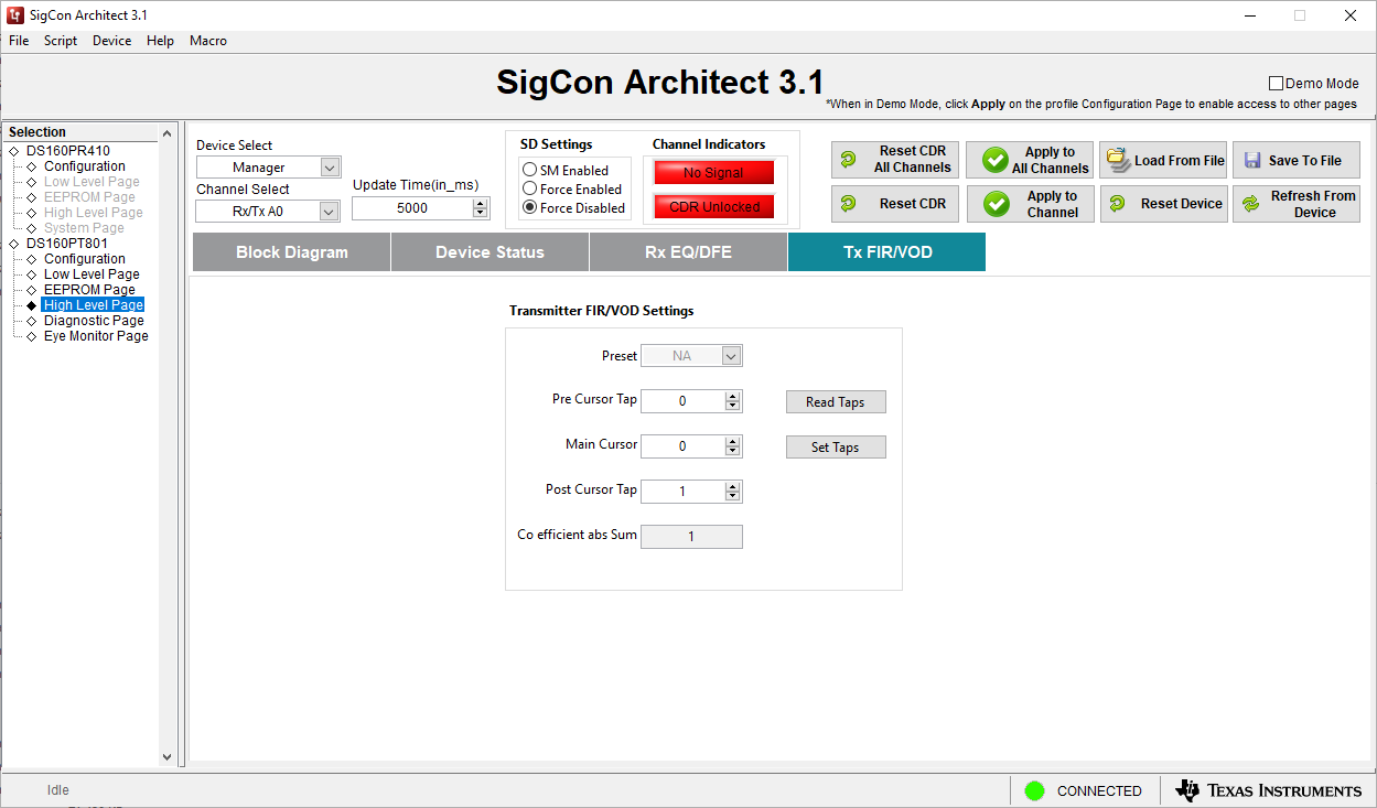 Figure 3-9 High-Level Page Tx
FIR
Figure 3-9 High-Level Page Tx
FIRThe Tx FIR/VOD tab allows a user to control the coefficient values of the FIR filter at the transmitter of the DS160PT801. These values are auotmatically negotiated through the PCIe protocol, manually changing them would cause the retimer to operate outside of specification. For this reason the FIR values should only be changed when the retimer is not actively participating in PCIe protocol, such as while using the PRBS generator.
- Preset Dropdown changes the PCIe preset value of the DS160PT801's transmitters. This will update the pre, post, and main cursor value.
- Pre Cursor Tap Field sets the pre cursor value for the Tx FIR.
- Main Cursor Field sets the main cursor value for the Tx FIR.
- Post Cursor Tap Field sets the post cursor value for the Tx FIR.
- Co efficient abs Sum Field displays the absolute value of the Pre, Post, and Main cursor.
- Read Taps Button reads the current value of the Tx FIR taps.
- Set Taps Button set the Tx FIR tap values to what is currently shown in the GUI.