SLVAF52B July 2021 – November 2021 AFE8092 , TPS62913
2.1 AFE80xx Noise and Ripple Requirements
The AFE80xx is a family of high performance, wide bandwidth multi-channel transceivers, integrating eight RF sampling transmitter chains, eight RF sampling receiver chains, and up to two RF sampling digitizing auxiliary chains (feedback paths). The high dynamic range of the transmitter and receiver chains allows the device to generate and receive 3G, 4G, and 5G signals from wireless base stations, while the wide bandwidth capability of the AFE80xx devices is designed for multi-band 4G and 5G base stations.
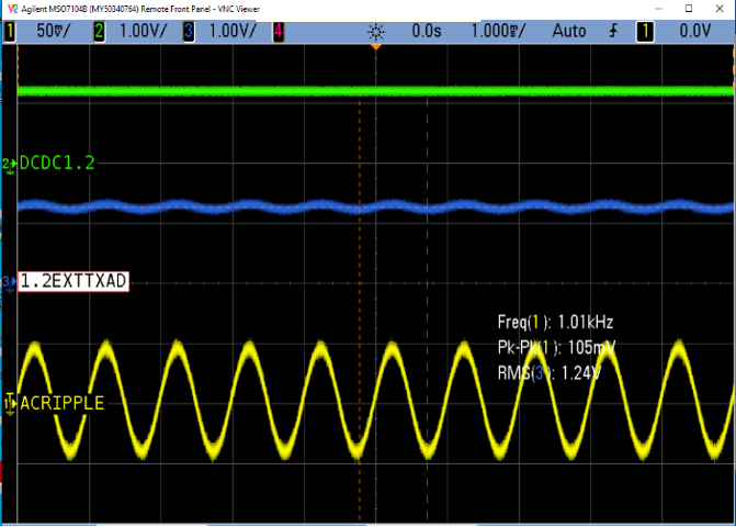
While the DC supply rail accuracy is specified for the AFE80xx, for ripple and noise specifications power supply to signal modulation (or PSMR) is used. In this application note 1.2-V TXADOUT and 1.8-V PLL is modulated with 100-mV peak to peak sine wave from 100 Hz to 2 MHz (600 kHz for 1.8-V PLL) signal frequency using Power Supply Line Injector to observe RF signal first order inter-modulation spurious amplitude.
To plot PSMR, spurious Root Mean Square (RMS) voltage is calculated using measured value of first harmonic power spectrum as shown in Equation 1 for 50-Ω load.
Than PSMR is than computed using ratio as shown in Equation 2 with RMS of injected supply ripple voltage (35.35 mV).
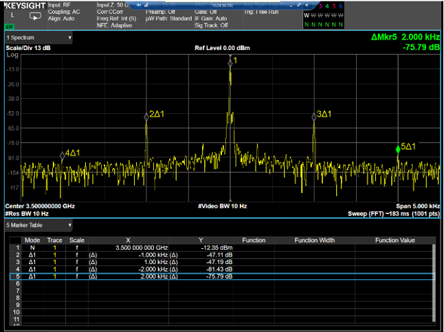
As an example shown in Figure 2-1 the 100-mV p-p sine wave signal impacts signal spectrum with undesired multiplicative inter-modulation spurious at offset of ripple frequency and its harmonic which impacts Signal SFDR for occupied bandwidth. This spurious can also corrupt constellation resulting in poor EVM.
 Figure 2-1 Modulated Power Supply 1.2
V
 Figure 2-2 TXA Output Spectrum for
Single Tone
Figure 2-2 TXA Output Spectrum for
Single ToneConsolidated Power Supply Modulation Ratio (or PSMR for 1.2-V TXADOUT and 1.8-V PLL is as shown in Figure 2-3 and Figure 2-4. For 1.2-V TX Supply PSMR indicates sensitivity for low frequency ripple and higher attenuation for power supply switching frequency, thus it is necessary to limit undershoot and overshoot and steady state ripple due to low frequency load transient.
Signal to Noise Ratio (SNR) to EVM can be understood using Modulation Error Rate (MER) which can be related using peak to average power ratio (dB) of modulation scheme and target EVM specification for non-averaged measurement as shown in Equation 3. For 64 Quadrature Amplitude Modulation (QAM) having 3.7-dB peak to average ratio and 0.3% target EVM, the SNR needs to be approximately -47 dB.
For 1.2-V TX DAC supply at 100 Hz for 35.35-mV RMS supply ripple the PSMR magnitude is close to -42 dB resulting in spurious magnitude of -59.96 dBm in power spectrum. For -12-dBm carrier tone and -48-dB allowed power supply spurious magnitude, the load transient ripple on 1.2-V TX supply needs to be below 35.35 mV to achieve desired EVM specification.
For 1.8-V PLL the PSMR plot indicates that supply ripple is amplified up to 200-kHz bandwidth post which the ripple is attenuated, hence the 1.8-V PLL needs to be powered using low noise and ripple free power circuitry.
 Figure 2-3 PSMR 1.2-V TXADOUT
 Figure 2-4 PSMR 1.8-V PLL
3-GPP TS 136 104 5G NR standard recommends EVM limit of 8% for 64-QAM modulation and 3.5% for 256 QAM for base station type 1-C and 1-H.
For this application note noise floor below -90 dB and power supply side band inter-modulation spurious magnitude below -46 dB with respect to carrier tone is considered as desired specification to meet below 2% target of first symbol EVM to comply with 5G NR standard requirements.
To meet the above desired specification, fixed frequency control topology is used to maintain steady state switching frequency ripple across load current variation. Second stage filtering is added in DC-DC power path to attenuate switching frequency supply ripple below 1 mV. Step load transient ripple (Overshoot and Undershoot) is maintained below 35.35 mV to achieve below -47-dB target for supply inter-modulation spurious with RF signal tone.