SLVAF10 March   2021 TPS1H000-Q1 , TPS1H100-Q1 , TPS1H200A-Q1 , TPS1HA08-Q1 , TPS1HB08-Q1 , TPS1HB16-Q1 , TPS1HB35-Q1 , TPS1HB50-Q1 , TPS2H000-Q1 , TPS2H160-Q1 , TPS2HB16-Q1 , TPS2HB35-Q1 , TPS2HB50-Q1 , TPS4H000-Q1 , TPS4H160-Q1


  1.   Trademarks
  2. 1Introduction
  3. 2Device Thermals
  4. 3Timing Limitations
    1. 3.1 Background
    2. 3.2 Pulse-Width distortion (PWD)
      1. 3.2.1 Timing Impact of Delay Mismatch
      2. 3.2.2 Power Impact of Delay Mismatch on Resistive Loads
    3. 3.3 Finite Slew Rate
      1. 3.3.1 Timing Impact of Finite Slew Rate and Slew Rate Mismatch
      2. 3.3.2 Impact of Finite Slew Rate on Resistive Load Power
      3. 3.3.3 Impact of Slew Rate on LED Power
  5. 4System-Level Considerations
    1. 4.1 Diagnostics and Protection
      1. 4.1.1 Analog Current Sense
    2. 4.2 Dimming Ratio
    3. 4.3 Side-Stepping Frequency Limitations
  6. 5References

Dimming Ratio

One key advantage of PWM is the ability to change the average output of the energy dissipated by the load by varying only the duty cycle. Systems may need a wide range luminous or thermal outputs which helps define the duty cycle range.

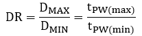
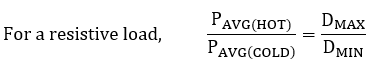
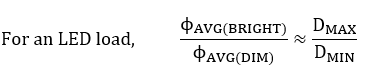
This is commonly referred to as the dimming ratio or contrast ratio in lightning applications. Dimming ratio, DR, is proportional to the power dissipated in a resistive element and the luminous flux of an LED.

Equation 47. GUID-AF383C77-B69F-4B98-9814-457764873622-low.png
Equation 47. GUID-E51373FA-3B8F-42AE-92FE-692784E4E2F1-low.png
Equation 47. GUID-A8963729-E635-44E6-826C-D9D87AC8F111-low.png
For DIM and COLD extremes of operation, the pulse widths will be the smallest. High side switch timing limitations on minimum pulse width are used to set DMIN and PWM frequency.