SLUUCC3 february 2021 BQ79631-Q1
- 1
- Abstract
- Trademarks
- General Texas Instruments High Voltage Evaluation (TI HV EVM) User Safety Guidelines
- 1General Description
- 2Theory of Operation
- 3Connectors
- 4Quick Start Guide
- 5Physical Dimensions
- 6BQ79631-Q1 EVM Schematic, Assembly, Layout, and BOM
2 Theory of Operation
The BQ79631-Q1 is designed to verify the safe operation of charging, discharging, and power transfer to a load in an EV/HEV system. Various voltage sense measurements are made at critical nodes within the BJB/BDU to make sure that the vehicle is operating as intended at all times. In a typical BMS system, a BQ79631-Q1 is used to gather critical data in the following areas:
- HV ±
- Link ±
- Charge ±
- HV_Fuse
- HV_Extra1_Plus/HV_Extra2_Plus
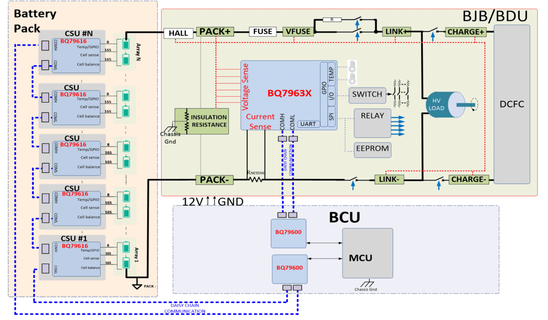
The typical BMS system with stacked modules has three main sub-systems, as shown in Figure 2-1:
- Host controller - in this case a TMS570 LaunchPad™.
- A BQ79631-Q1 configured as an isolated communication bridge device - a BQ79600EVM , BQ79616EVM, or a BQ79631EVM can also support this .
- BQ79616EVM based modules attached to cells - these can be stacked up to 35 total devices (including the bridge device).
 Figure 2-1 Typical BMS System with Stacked Modules
All commands and data are communicated with a host through either a UART or daisy-chain communication connection. The BQ79631 remains idle until a command is received from the host. The BQ79631 can support a host PC or microcontroller (through the UART connection header) or a daisy-chain interface from a BQ79600 implemented as a communication bridge.
The typical flow is for the host to go through the following simplified sequence:
- Wakeup the BQ79631EVM board by sending a WAKEUP pulse when using the UART interface, or send a WAKE tone when using the BQ79631EVM in a stack with other BQ79616EVM boards for a large battery pack. (Typically an auto address signal is needed if using the BQ79631EVM in a stack of other BQ devices but is not needed if using a single BQ79631EVM).
- Send a sample command to the BQ79631-Q1 to read the voltage measurement results.
- If no stop command is sent, then the BQ79631-Q1 has a built-in timeout (set by the user), after which time the discharge is stopped automatically.
- The host can then decide to repeat the process (back to step 2) or send commands to shutdown the BQ79631EVM and return later.