SLAU533D September 2013 – April 2017
-
MSP430F5529 LaunchPad™ Development Kit (MSP‑EXP430F5529LP)
- Trademarks
- 1 Getting Started
- 2
Hardware
- 2.1 Block Diagram
- 2.2
Hardware Features
- 2.2.1 MSP430F5529
- 2.2.2 eZ-FET lite Onboard Emulator
- 2.2.3 Integrated Full-Speed USB Hub
- 2.2.4 Power
- 2.2.5 Clocking
- 2.2.6 Application (or "Backchannel") UART
- 2.2.7 Emulator and Target Isolation Jumper Block
- 2.2.8 Isolation Jumper Block: 3.3-V and 5-V Jumpers
- 2.2.9 Isolation Jumper Block: Emulator Connection and Application UART
- 2.3 Measure Current Draw of MSP430 MCU
- 2.4 Using an External Power Source
- 2.5 Using the eZ-FET lite Emulator With a Different Target
- 2.6 USB BSL Button
- 2.7 BoosterPack Plug-in Module Pinout
- 2.8 Design Files
- 2.9 Hardware Change Log
- 3
Software Examples
- 3.1 MSP430 Software Libraries: driverlib and the USB API
- 3.2 Viewing the Code
- 3.3 Example Project Software Organization
- 3.4 USB Configuration Files
- 3.5 Out-of-Box Experience: emulStorageKeyboard
- 3.6 Example: simpleUsbBackchannel
- 3.7 Starting Device Manager
- 4 Additional Resources
- 5 FAQs
- 6 Schematics
- Revision History
2.6 USB BSL Button
Like the vast majority of MSP430 MCUs, the F5529 has an on-chip bootloader (BSL). The BSL is a program that resides in a special protected location in the MCU flash memory and facilitates communication with an external host. Like tools with JTAG access, it can read and write the MCU flash memory. But unlike JTAG tools, it cannot be used to emulate code.
The interface to the BSL is often a UART or sometimes I2C. On USB-equipped derivatives, the BSL interface is USB.
In situations where JTAG access is not available, the BSL plays an important role in accessing the device. For example, it can be used to recover the device when something has corrupted internal flash. It is often used for products in the field, when there is no JTAG access. Because of the use in the field, the BSL is password-protected, which prevents unwanted access to proprietary application software. To serve its role in updating MSP430 flash memory, the BSL must be invoked, meaning that execution must be transferred to it. This can happen a few different ways, but on the USB BSL, one way is to pull the PUR pin high immediately after a BOR reset.
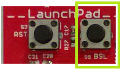
The USB BSL button on the F5529 LaunchPad development kit (see Figure 21) serves this purpose.
 Figure 21. USB BSL Button
 Hold the button down while attaching the F5529 LaunchPad development kit to the USB host, continue to hold it for approximately one second after attaching, and then release. (This assumes the F5529 LaunchPad development kit was unpowered prior to attaching, which allows a power-up event to occur.) The target F5529 should enumerate under USB BSL control as a HID interface. The USB BSL has its own vendor ID (VID) and product ID (PID), the codes used in USB to separate one USB product from another. The BSL VID and PID pair is 0x2047 and 0x0200.
In Device Manager, the HID interface can be found under the "Human Interface Devices" group. (See Section 3.7 for instructions on starting Device Manager.) If you open Device Manager prior to attaching the LaunchPad development kit as described above, you will see it refresh, and then two new entries appear: "HID-compliant device" and "USB Input Device". Both refer to the one HID interface presented by the USB BSL.
These are generic names that can also appear for other HID devices. To be completely sure these entries derive from the USB BSL, you can look for the VID and PID associated with them, and make sure they are 0x2047 and 0x0200. For every such entry under the "Human Interface Devices" group, right-click on the entry, then click Properties, then go to the "Details" tab, and select "Hardware IDs" from the pulldown menu (see Figure 22).
 Figure 22. Identifying the USB BSL HID Interface in Device Manager
 For every other HID interface entry, the IDs in the "Value" field are different. For the USB BSL, they include the strings "VID_2047" and "PID_0200".
If these interface entries do not appear, then something went wrong in the procedure to press the USB BSL button to invoke the BSL. Retry the procedure.
After this interface enumerates, a host application is needed to interface with it and issue BSL commands to access the firmware on the MSP430 MCU. The MSP430 USB Developers Package includes a firmware updater application that uses the USB BSL to download programs. For its input, it uses TI-TXT object-code files. TI-TXT is a simple text-based object-code format that used with MSP430 MCUs to store and distribute compiled code. These files can be generated by CCS or IAR. TI-TXT files for the software examples are included in the zip file (\bin\simpleBackchannel.txt and \bin\emulStorageKeyboard.txt).
See the application report USB Field Firmware Updates on MSP430 MCUs for information about designing firmware update into your USB application. Additional information about the MSP430 BSL can be found in the MSP430 Programming With the Bootloader (BSL).