SLAU330B May 2011 – April 2017
- Read This First
- MSP-EXP430F5529 Experimenter's Board
- Revision History
3.3 Working With the Example Software
The MSP-EXP430F5529 example software is written in C and offers APIs to control the MSP430F5529 chip and external components on the MSP-EXP430F5529 Experimenter's Board. New application development can use this library for guidance.
The example software can be downloaded from the MSP-EXP430F5529 tools page, MSP-EXP430F5529 Experimenter's Board User Experience Software. The zip package includes the MSP-EXP430F5529 example software. The code is ready for compilation and execution.
To modify, compile, and debug the example code the following steps should be followed:
- If you have not already done so, download the sample code from the MSP-EXP430F5529 tools page.
- Install 5529UE-x.xx-Setup.exe installation package to the PC.
- Connect the MSP-FET430UIF programmer to the PC. If you have not already done so, install the drivers for the programmer.
- Connect one end of the 14-pin cable to JTAG programmer and another end to the JTAG header on the board.
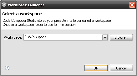
- Open CCS and select a workspace directory (see Figure 3).
 Figure 3. Selecting a CCS Workspace
 - Select Project > Import Existing CCS/CCE Eclipse Project.
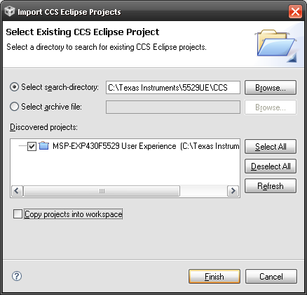
- Browse to the extracted project directory. The project should now show up in the Projects list (see Figure 4).
- Make sure the project is selected, and click Finish.
 Figure 4. Opening Existing Project
 The project is now open. To build, download, and debug the code on the device on the MSP-EXP430F5529 Experimenter's Board, select Target > Debug Active Project or click the green 'bug' button.
You may be prompted to update the firmware on the MSP-FET430UIF programmer. Do not be concerned; click the button that says Update, and the program download should continue as expected.
NOTE
To begin developing your own application, follow these steps:
- Download and install a supported IDE:
- Connect the MSP-EXP430F5529 Experimenter's Board "eZ-FET" USB to the PC.
- Download and debug your application.
Code Composer Studio – Free 16KB IDE: www.ti.com/ccs
IAR Embedded Workbench KickStart – Free 8KB IDE: www.ti.com/iar-kickstart