SLAU330B May 2011 – April 2017
- Read This First
- MSP-EXP430F5529 Experimenter's Board
- Revision History
4.2 Jumper Settings and Power
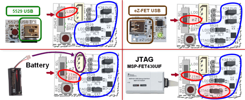
Figure 7 shows the common jumper settings, depending on the power source for the MSP-EXP430F5529 Experimenter's Board.
 Figure 7. Common Power Jumper Settings
 There are also other jumpers available for current measurement, disconnection of certain peripherals, and other advanced options (see Table 1). The black line on the board below the jumpers JP8 (LDO) and JP11 (JTAG) indicates the default jumper position.
Table 1. MSP-EXP430F5529 Jumper Settings and Functionality
| Header | Functionality When Jumper Present | Functionality When Jumper Absent |
|---|---|---|
| JP2 – POT | Connects pin P8.0 to potentiometer | Disconnects pin P8.0 to potentiometer |
| JP3 – LED1 | Connects pin P1.0 to LED1 | Disconnects pin P1.0 to LED1 |
| JP6 – 430 PWR |
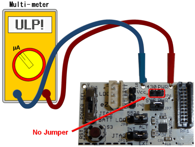
Provides power to MSP430F5529. Also used to measure current consumption of the MSP430F5529. NOTE The two large vias near the "430 PWR" label on the PCB are connected to JP6 as well. These vias can be used to easily connect a test lead onto the PCB for current consumption measurement. |
MSP430F5529 is not powered. |
| JP7 – SYS PWR | Provides power to the entire MSP-EXP430F5529 board. Also used to measure current consumption of the entire board. | MSP-EXP430F5529 Experimenter's Board system devices are not powered. |
| JP8 – LDO |
Only applicable when powering through "5529 USB" connection. ALT (Default): Connects the alternate LDO (TPS73533) to the MSP430 VCC. INT: Connects the internal 'F5529 LDO to the MSP430 VCC. |
No connection to MSP430 VCC when powered through "5529 USB". |
| JP11 – JTAG |
Only applicable when powering through JTAG connection. EXT (Default): JTAG tool does NOT provide power to system. INT: JTAG tool will provide power to system. |
JTAG tool does NOT provide power to system. |
| JP14 – RF PWR | Connects system VCC to the RF headers: J12, J13, and RF2. | RF headers: J12, J13, and RF2 do not have power. |
| JP15 – USB PWR | Connects USB 5-V power to MSP430F5529 and Alternate LDO (TPS73533). | USB 5-V power not connected to system. |
| JP16 – eZ-FET Connection |
DVCC: Connects MSP430 VCC to eZ-FET TXD / RXD: Connects UART between F5529 and eZ-FET. RST / TEST: Connects Spy-Bi-Wire JTAG between F5529 and eZ-FET. |
No connection between MSP430F5529 and the eZ-FET. |
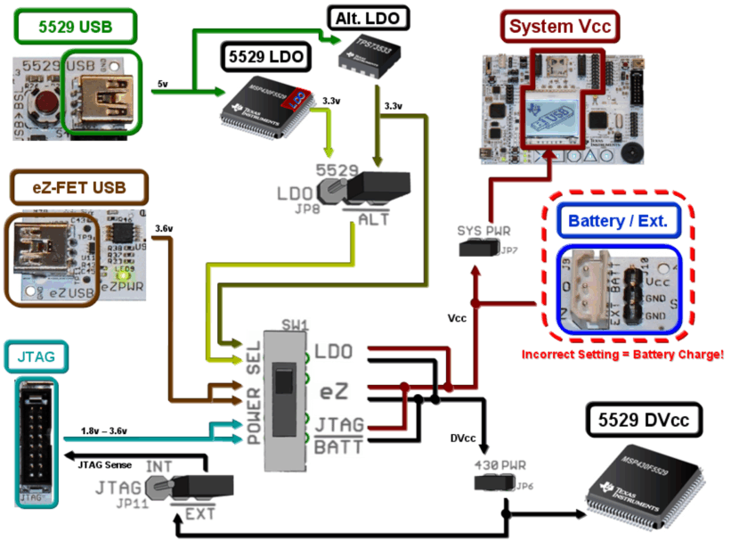
Figure 8 shows a visual diagram of the power connections for the MSP-EXP430F5529 Experimenter's Board. Care should be observed when using multiple power sources such as USB and a battery at the same time. This could lead to the battery being charged if the power settings are not correct.
 Figure 8. Visual Power Schematic
 Figure 9 shows a method of connecting a multimeter to the MSP-EXP430F5529 to measure the current of the MSP430F5529.
 Figure 9. MSP430 Current Measurement Connection