SLAU330B May   2011  – April 2017


  1.   Read This First
    1.     If You Need Assistance
    2.     Related Documentation from Texas Instruments
    3.     Trademarks
  2.   MSP-EXP430F5529 Experimenter's Board
    1. 1 Getting Started
      1. 1.1 MSP-EXP430F5529 Experimenter's Board Introduction
      2. 1.2 Kit Contents
    2. 2 User Experience Software
      1. 2.1 Introduction
      2. 2.2 Main Menu
      3. 2.3 Clock
      4. 2.4 Games
      5. 2.5 Power Tests
      6. 2.6 Demo Apps
      7. 2.7 SD Card Access
      8. 2.8 Settings Menu
    3. 3 Software Installation and Debugging
      1. 3.1 Software
      2. 3.2 Download the Required Software
      3. 3.3 Working With the Example Software
        1. 3.3.1 Basic Code Structure
    4. 4 MSP-EXP430F5529 Hardware
      1. 4.1 Hardware Overview
      2. 4.2 Jumper Settings and Power
      3. 4.3 eZ-FET Emulator
      4. 4.4 MSP-EXP430F5529 Hardware Components
        1. 4.4.1 Dot-Matrix LCD
        2. 4.4.2 Push Buttons, Potentiometer, and LEDs
        3. 4.4.3 Wireless Evaluation Module Interface
        4. 4.4.4 eZ430-RF2500T Interface
        5. 4.4.5 3-Axis Accelerometer
        6. 4.4.6 Pin Access Headers
    5. 5 Frequently Asked Questions, References, and Schematics
      1. 5.1 Frequently Asked Questions
      2. 5.2 References
      3. 5.3 Schematics and BOM
  3.   Revision History

Hardware Overview

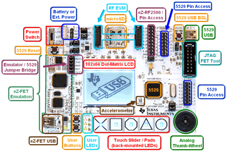
Figure 5 and Figure 6 show the functional blocks and connections of the MSP-EXP430F5529 Experimenter's Board. The area of the PCB labeled as "eZ430-FET Emulator" and bordered by a thick broken line on the PCB silk screen is an integrated TI Flash Emulation Tool (FET) which is connected to the Experimenter's Board by the jumpers on JP16. This module is similar to any eZ430 emulator, and provides real-time in-system Spy-Bi-Wire programming and debugging through a USB connection to a PC. Using the eZ430-FET Emulator module eliminates the need for using an external MSP430 Flash Emulation Tool (MSP-FET430UIF). However, full speed 4-wire JTAG communication is only possible with a MSP-FET430UIF connected to the "5529 JTAG" header. For additional details on the installation and usage of the Flash Emulation Tool, Spy-Bi-Wire and JTAG, see the MSP430 Hardware Tools User's Guide.
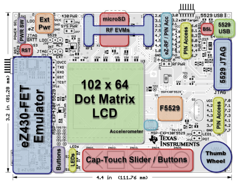
simple_hardware_overview_slau330.gifFigure 5. Simple Hardware Overview
hardware_block_details_slau330.gifFigure 6. Hardware Block Details