SLAA721E October 2016 – March 2020 MSP430FR5969 , MSP430FR5969-SP , MSP430FR5994 , MSP430FR6989
- Trademarks
- 1Introduction
- 2Implementation
- 3Customization of MSP430FRBoot
- 4Building MSPBoot
- 5Demo Using FRAM LaunchPad Development Kit as Host
- 6Porting the target side example projects to other MSP430FR devices
- 7References
- 8Revision History
6 Porting the target side example projects to other MSP430FR devices
This section lists an example of steps to porting the target side example projects to other MSP430FR devices. Take the MSP430FR2355 in IAR and use UART single image mode as an example.
-
Choose FR2433_UART_Single target demo projects as the template. The demo project is located at "MSP430FRBoot_<version>\Target_IAR\MSP430FR2433_TARGET\FR2433_UART_Single".
-
Copy the "FR2344_UART_Single" project and the linker folder named "FR2433_Linker_files" into another folder, as shown in Figure 6-1. For MSP430fr2xx4xx family devices, choose the MSP430FR2433 target demo projects as a template. For MSP430FR5xx6xx family devices, choose the MSP430FR5969 target demo projects.
 Figure 6-1 Copy UART single project and the linker folder to other folder
 -
Open FR2344_UART_Single project folder. Change the workspace name from "MSP430FR2433_UART_Single" to "MSP430FR2355_UART_Single" (based on your device).
 Figure 6-2 Change the workspace name
 -
Open the workspace and the three included projects.
-
"App1_UART_Single" uses a button to jump from application to boot code.
-
"App2_UART_Single" uses UART to receive a jump command, then jump from application to boot code.
-
"Boot_UART_Single" is the boot side code.
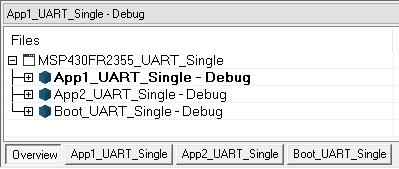 Figure 6-3 Projects in the
workspace
-
-
Modify the projects based on your application case, like different PGIOs or UART interfaces.
-
Choose boot project "Boot_UART_Single" and search "//Need to change" in the whole project to find the files that need to be modified, as shown below.
 Figure 6-4 Find results in
the boot project
 -
Open the files that need to be changed.
-
Search "//Simple change" in each file to find the area that needs to be modified, based on your application. Figure 6-5 shows a search in "main.c". You need to change the registers and GPIOs based on your application. (For more details about how to make the change, you can compare the differences between MSP430FR2433, MSP430FR5969, and MSP430FR5994)
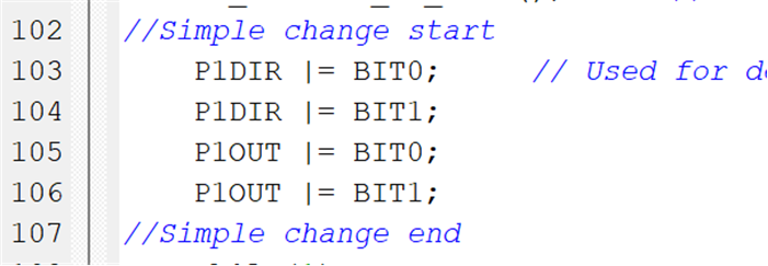 Figure 6-5 Find the result of
the simple change to change the GPIO
 -
Make the same modification in the "App1_UART_Single" or "App2_UART_Single" projects with the boot project as steps 5.a to 5.c.
-
-
Open the folder "Utilities\linkerGen" and read the file "Readme.txt" to know how to generate the linker files based on your device.
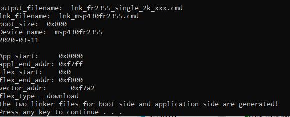 Figure 6-6 Generate the linker file
successfully MSP430FR2355
 -
Delete the linker files for MSP430FR2433 in the linker folder "FR2433_Linker_files" and copy the newly generated linker files into this folder.
 Figure 6-7 Move the linker file to the folder
 -
Open the boot project "Boot_UART_Single" options.
-
Change the device to MSP430FR2355 (based on your device).
-
Change the definition of "__MSP430FR2433__" to "__MSP430FR2355__".
-
Change the newly genreated linker file's name.
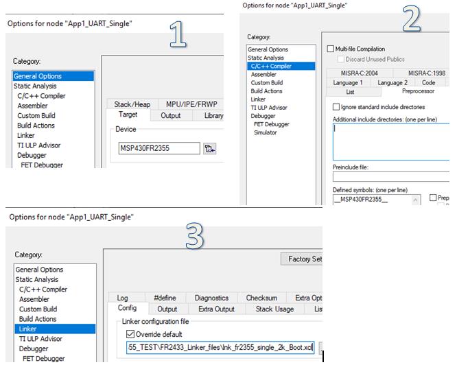 Figure 6-8 Configure the project
option
 -
-
Build the application project to generate the .txt file.
-
Convert the .txt file into a .c file by using the tools in folder "Utilities\430txt_converter". This makes the image file easy for the host project to use.
 Figure 6-9 Generate the .txt file and convert it to a .c file
 -
Copy the .c files generated by the converter into the host project folder "MSP430FR2433_Host\TargetApps"
-
Open the host project named "UART_Single".
-
Change the .c file's name used in step 10, as shown in Figure 6-10
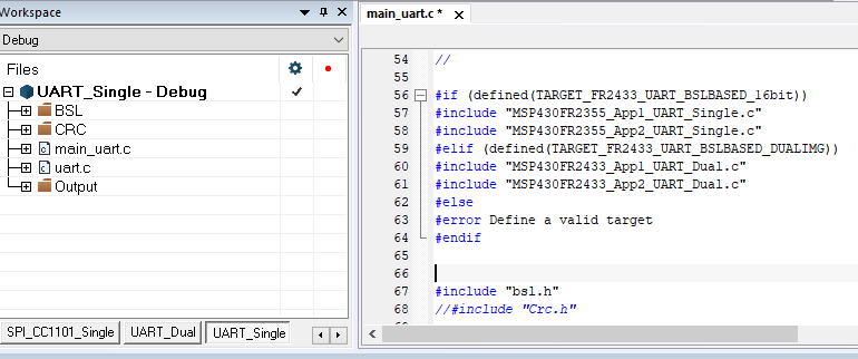 Figure 6-10 Change the
image name in the host
 - Change the start address of
the CRC_Addr to 0x8000, which is the start FRAM address of MSP430FR2355, and
the App_StartAddress to 0x8002. (For CCS projects, App_StartAddress should
be change to 0x8003.)
 Figure 6-11 Change the address information
 - If you only have App1 and don't have App2, you can comment the code "sentBSLFlipFlop = !sentBSLFlipFop;" to make the host download App1 only.
-
-
Test the code in hardware. If you want to debug your application code, you can use the normal linker file first (maybe some variable undefined error, just comment them). After debugging, change it back to the linker file generated by the Python scripter.