ZHCSLQ5D October   2007  – August 2020 LM5067

PRODUCTION DATA  

  1. 特性
  2. 应用
  3. 说明
  4. Revision History
  5. Device Comparison
  6. Pin Configuration and Functions
    1.     Pin Functions
  7. Specifications
    1. 7.1 Absolute Maximum Ratings
    2. 7.2 ESD Ratings
    3. 7.3 Recommended Operating Conditions
    4. 7.4 Thermal Information
    5. 7.5 Electrical Characteristics
    6. 7.6 Switching Characteristics
    7. 7.7 Typical Characteristics
  8. Detailed Description
    1. 8.1 Overview
    2. 8.2 Functional Block Diagram
    3. 8.3 Feature Description
      1. 8.3.1 Power Up Sequence
      2. 8.3.2 Gate Control
      3. 8.3.3 Current Limit
      4. 8.3.4 Circuit Breaker
      5. 8.3.5 Power Limit
      6. 8.3.6 Fault Timer and Restart
      7. 8.3.7 Undervoltage Lock-Out (UVLO)
      8. 8.3.8 Overvoltage Lock-Out (OVLO)
      9. 8.3.9 Power Good Pin
    4. 8.4 Device Functional Modes
      1. 8.4.1 Shutdown / Enable Control
  9. Application and Implementation
    1. 9.1 Application Information
    2. 9.2 Typical Application
      1. 9.2.1 Design Requirements
      2. 9.2.2 Detailed Design Procedure
        1. 9.2.2.1  RIN, CIN
        2. 9.2.2.2  Current Limit, RS
        3. 9.2.2.3  Power Limit Threshold
        4. 9.2.2.4  Turn-On Time
          1. 9.2.2.4.1 Turn-on With Current Limit Only
          2. 9.2.2.4.2 Turn-on With Power Limit and Current Limit
        5. 9.2.2.5  MOSFET Selection
        6. 9.2.2.6  Timer Capacitor, CT
          1. 9.2.2.6.1 Insertion Delay
          2. 9.2.2.6.2 Fault Timeout Period
          3. 9.2.2.6.3 Restart Timing
        7. 9.2.2.7  UVLO, OVLO
          1. 9.2.2.7.1 Option A:
          2. 9.2.2.7.2 Option B:
          3. 9.2.2.7.3 Option C:
          4. 9.2.2.7.4 Option D:
        8. 9.2.2.8  Thermal Considerations
        9. 9.2.2.9  System Considerations
          1. 9.2.2.9.1 System Considerations During Surge Events
        10. 9.2.2.10 Power Good Pin
      3. 9.2.3 Application Curves
  10. 10Power Supply Recommendations
    1. 10.1 Operating Voltage
  11. 11Layout
    1. 11.1 Layout Guidelines
    2. 11.2 Layout Example
  12. 12Device and Documentation Support
    1. 12.1 Trademarks
    2. 12.2 静电放电警告
    3. 12.3 术语表
  13. 13Mechanical, Packaging, and Orderable Information

封装选项

机械数据 (封装 | 引脚)
散热焊盘机械数据 (封装 | 引脚)
订购信息

说明

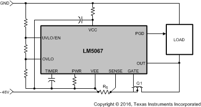
LM5067 负电压热插拔控制器可在从带电系统背板或其他“热插拔”电源插入和移除电路板期间,为电源连接提供智能控制,并通过提供浪涌电流控制来限制系统电压下降和瞬变。外部串行导通 N 沟道 MOSFET 中的电流限制和功率耗散可进行编程,从而确保其在安全工作区 (SOA) 内工作。此外,LM5067 可监控过流和过压状况,从而提供电路保护。当输出电压接近输入电压时,会显示电源正常输出。输入欠压和过压锁定电平和迟滞,以及故障监测时间均可进行编程。LM5067-1 在检测到故障之后闭锁,同时 LM5067-2 以固定占空比自动尝试重启。LM5067 采用 10 引脚 VSSOP 封装和 14 引脚 SOIC 封装。

器件信息(1)
器件型号封装封装尺寸(标称值)
LM5067VSSOP (10)3.00mm x 3.00mm
SOIC (14)8.99mm x 7.49mm
如需了解所有可用封装,请参阅数据表末尾的可订购产品附录。
GUID-A54992F7-B386-43E1-9FCF-D44052A429FB-low.gif负电源总线浪涌和故障保护